Last Updated on March 23, 2018 by Admin
6.1.2.7 Packet Tracer – Investigating a VLAN Implementation
From year to year, Cisco has updated many versions with difference questions. The latest version is version 6.0 in 2018. What is your version? It depends on your instructor creating your class. We recommend you to go thought all version if you are not clear. While you take online test with netacad.com, You may get random questions from all version. Each version have 1 to 10 different questions or more. After you review all questions, You should practice with our online test system by go to "Online Test" link below.
Packet Tracer – Investigating a VLAN Implementation (Answer Version)
Answer Note: Red font color or Gray highlights indicate text that appears in the Answer copy only.
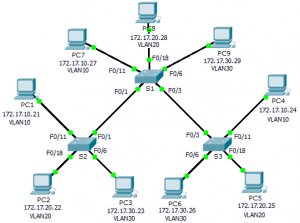
Topology

6.1.2.7 Packet Tracer – Investigating a VLAN Implementation
Addressing Table
| Device | Interface | IP Address | Subnet Mask | Default Gateway |
| S1 | VLAN 99 | 172.17.99.31 | 255.255.255.0 | N/A |
| S2 | VLAN 99 | 172.17.99.32 | 255.255.255.0 | N/A |
| S3 | VLAN 99 | 172.17.99.33 | 255.255.255.0 | N/A |
| PC1 | NIC | 172.17.10.21 | 255.255.255.0 | 172.17.10.1 |
| PC2 | NIC | 172.17.20.22 | 255.255.255.0 | 172.17.20.1 |
| PC3 | NIC | 172.17.30.23 | 255.255.255.0 | 172.17.30.1 |
| PC4 | NIC | 172.17.10.24 | 255.255.255.0 | 172.17.10.1 |
| PC5 | NIC | 172.17.20.25 | 255.255.255.0 | 172.17.20.1 |
| PC6 | NIC | 172.17.30.26 | 255.255.255.0 | 172.17.30.1 |
| PC7 | NIC | 172.17.10.27 | 255.255.255.0 | 172.17.10.1 |
| PC8 | NIC | 172.17.20.28 | 255.255.255.0 | 172.17.20.1 |
| PC9 | NIC | 172.17.30.29 | 255.255.255.0 | 172.17.30.1 |
Objectives
Part 1: Observe Broadcast Traffic in a VLAN Implementation
Part 2: Observe Broadcast Traffic without VLANs
Part 3: Complete Reflection Questions
Background
In this activity, you will observe how broadcast traffic is forwarded by the switches when VLANs are configured and when VLANs are not configured.
Part 1:Observe Broadcast Traffic in a VLAN Implementation
Step 1: Ping from PC1 to PC6.
- Wait for all the link lights to turn to green. To accelerate this process, click Fast Forward Time located in the bottom yellow tool bar.
- Click the Simulation tab and use the Add Simple PDU tool. Click on PC1, and then click on PC6.
- Click the Capture/Forward button to step through the process. Observe the ARP requests as they traverse the network. When the Buffer Full window appears, click the View Previous Events button.
- Were the pings successful? Why? No, the pings were not successful because PC1 is on a different VLAN than PC6, which won’t allow these devices to communicate with each other because they are separated logically.
- Look at the Simulation Panel, where did S3 send the packet after receiving it? S3 sent it to PC4 because it was on the same VLAN as PC1.
In normal operation, when a switch receives a broadcast frame on one of its ports, it forwards the frame out all other ports. Notice that S2 only sends the ARP request out Fa0/1 to S1. Also notice that S3 only sends the ARP request out F0/11 to PC4. PC1 and PC4 both belong to VLAN 10. PC6 belongs to VLAN 30. Because broadcast traffic is contained within the VLAN, PC6 never receives the ARP request from PC1. Because PC4 is not the destination, it discards the ARP request. The ping from PC1 fails because PC1 never receives an ARP reply.
Step 2: Ping from PC1 to PC4.
- Click the New button under the Scenario 0 dropdown tab. Now click on the Add Simple PDU icon on the right side of Packet Tracer and ping from PC1 to PC4.
- Click the Capture/Forward button to step through the process. Observe the ARP requests as they traverse the network. When the Buffer Full window appears, click the View Previous Events button.
- Were the pings successful? Why? Yes, because PC1 and PC4 both belong to VLAN 10, so the path of the ARP request is the same as before. Because PC4 is the destination, it replies to the ARP request. PC1 is then able to send the ping with the destination MAC address for PC4.
- Examine the Simulation Panel. When the packet reached S1, why does it also forward the packet to PC7? Because PC7 also belong to VLAN 10 and the ARP requests was for VLAN10, switches will forward to any devices that are connected to VLAN10 in their port.
Part 2: Observe Broadcast Traffic without VLANs
Step 1: Clear the configurations on all three switches and delete the VLAN database.
- Return to Realtime mode.
- Delete the startup configuration on all 3 switches. What command is used to delete the startup configuration of the switches? Switch# erase startup-config
- Where is the VLAN file stored in the switches? flash:vlan.dat
- Delete the VLAN file on all 3 switches. What command deletes the VLAN file stored in the switches? Switch# delete vlan.dat
Step 2: Reload the switches.
Use the reload command in privileged EXEC mode to reset all the switches. Wait for the entire link to turn green. To accelerate this process, click Fast Forward Time located in the bottom yellow tool bar.
Step 3: Click Capture/Forward to send ARP requests and pings.
- After the switches reload and the link lights return to green, the network is ready to forward your ARP and ping traffic.
- Select Scenario 0 from the drop down tab to return to Scenario 0.
- From Simulation mode, click the Capture/Forward button to step through the process. Notice that the switches now forward the ARP requests out all ports, except the port on which the ARP request was received. This default action of switches is why VLANs can improve network performance. Broadcast traffic is contained within each VLAN. When the Buffer Full window appears, click the View Previous Events button.
Part 3: Complete Reflection Questions
- If a PC in VLAN 10 sends a broadcast message, which devices receive it? All devices that are on VLAN 10
- If a PC in VLAN 20 sends a broadcast message, which devices receive it? All devices that are on VLAN 20
- If a PC in VLAN 30 sends a broadcast message, which devices receive it? All devices that are on VLAN 30
- What happens to a frame sent from a PC in VLAN 10 to a PC in VLAN 30? It will be dropped.
- In terms of ports, what are the collision domains on the switch? Each port is a separate collision domain.
- In terms of ports, what are the broadcast domains on the switch? They are divided by the number of VLANs in the switch.
From year to year, Cisco has updated many versions with difference questions. The latest version is version 6.0 in 2018. What is your version? It depends on your instructor creating your class. We recommend you to go thought all version if you are not clear. While you take online test with netacad.com, You may get random questions from all version. Each version have 1 to 10 different questions or more. After you review all questions, You should practice with our online test system by go to "Online Test" link below.
Suggested Scoring Rubric
| Activity Section | Question Location | Possible Points | Earned Points |
| Part 1: Observe Broadcast Traffic in a VLAN Implementation | Step 1d | 6 | |
| Step 1e | 5 | ||
| Step 2c | 6 | ||
| Step 2d | 5 | ||
| Part 1 Total | 22 | ||
| Part 2: Observe Broadcast Traffic without VLANs | Step 1b | 6 | |
| Step 1c | 6 | ||
| Step 1d | 6 | ||
| Part 2 Total | 18 | ||
| Part 3: Complete Reflection Questions | 1 | 10 | |
| 2 | 10 | ||
| 3 | 10 | ||
| 4 | 10 | ||
| 5 | 10 | ||
| 6 | 10 | ||
| Part 3 Total | 60 | ||
| Total Score | 100 | ||