Last Updated on March 13, 2018 by Admin
Appendix Packet Tracer – Subnetting Scenario 2
From year to year, Cisco has updated many versions with difference questions. The latest version is version 6.0 in 2018. What is your version? It depends on your instructor creating your class. We recommend you to go thought all version if you are not clear. While you take online test with netacad.com, You may get random questions from all version. Each version have 1 to 10 different questions or more. After you review all questions, You should practice with our online test system by go to "Online Test" link below.
Packet Tracer – Subnet Scenario 2 (Answer Version)
Answer Note: Red font color or Gray highlights indicate text that appears in the Answer copy only.
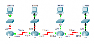
Topology

Appendix Packet Tracer – Subnetting Scenario 2
Addressing Table
| Device | Interface | IP Address | Subnet Mask | Default Gateway |
| R1 | G0/0 | 172.31.1.1 | 255.255.255.240 | N/A |
| S0/0/0 | 172.31.1.65 | 255.255.255.240 | N/A | |
| R2 | G0/0 | 172.31.1.17 | 255.255.255.240 | N/A |
| S0/0/0 | 172.31.1.78 | 255.255.255.240 | N/A | |
| S0/0/1 | 172.31.1.81 | 255.255.255.240 | N/A | |
| R3 | G0/0 | 172.31.1.33 | 255.255.255.240 | N/A |
| S0/0/0 | 172.31.1.97 | 255.255.255.240 | N/A | |
| S0/0/1 | 172.31.1.94 | 255.255.255.240 | N/A | |
| R4 | G0/0 | 172.31.1.49 | 255.255.255.240 | N/A |
| S0/0/0 | 172.31.1.110 | 255.255.255.240 | N/A | |
| S1 | VLAN 1 | 172.31.1.2 | 255.255.255.240 | 172.31.1.1 |
| S2 | VLAN 1 | 172.31.1.18 | 255.255.255.240 | 172.31.1.17 |
| S3 | VLAN 1 | 172.31.1.34 | 255.255.255.240 | 172.31.1.33 |
| S4 | VLAN 1 | 172.31.1.50 | 255.255.255.240 | 172.31.1.49 |
| PC1 | NIC | 172.31.1.14 | 255.255.255.240 | 172.31.1.1 |
| PC2 | NIC | 172.31.1.30 | 255.255.255.240 | 172.31.1.17 |
| PC3 | NIC | 172.31.1.46 | 255.255.255.240 | 172.31.1.33 |
| PC4 | NIC | 172.31.1.62 | 255.255.255.240 | 172.31.1.49 |
Objectives
Part 1: Design an IP Addressing Scheme
Part 2: Assign IP Addresses to Network Devices and Verify Connectivity
Scenario
In this activity, you are given the network address of 172.31.1.0 /24 to subnet and provide the IP addressing for the network shown in the Topology. The required host addresses for each WAN and LAN link are labeled in the topology.
Part 1: Design an IP Addressing Scheme
Step 1: Subnet the 172.31.1.0/24 network based on the maximum number of hosts required by the largest subnet.
- Based on the topology, how many subnets are needed? 7
- How many bits must be borrowed to support the number of subnets in the topology table? 4
- How many subnets does this create? 16
- How many usable host addresses does this create per subnet? 14
- Note: If your answer is less than the 14 maximum hosts required for the R3 LAN, then you borrowed too many bits.
- Calculate the binary value for the first five subnets. Subnet zero is already shown.
- Net 0: 172 . 31 . 1 . 0 0 0 0 0 0 0 0
- Net 1: 172 . 31 . 1 . ___ ___ ___ ___ ___ ___ ___ ___
- Net 1: 172 . 31 . 1 . 0 0 0 1 0 0 0 0
- Net 2: 172 . 31 . 1 . ___ ___ ___ ___ ___ ___ ___ ___
- Net 2: 172 . 31 . 1 . 0 0 1 0 0 0 0 0
- Net 3: 172 . 31 . 1 . ___ ___ ___ ___ ___ ___ ___ ___
- Net 3: 172 . 31 . 1 . 0 0 1 1 0 0 0 0
- Net 4: 172 . 31 . 1 . ___ ___ ___ ___ ___ ___ ___ ___
- Net 4: 172 . 31 . 1 . 0 1 0 0 0 0 0 0
- Calculate the binary and decimal value of the new subnet mask.
- 11111111.11111111.11111111. ___ ___ ___ ___ ___ ___ ___ ___
- 11111111.11111111.111111111. 1 1 1 1 0 0 0 0
- 255 . 255 . 255 . ______
- 255 . 255 . 255 . 240
- Complete the Subnet Table, listing all available subnets, the first and last usable host address, and the broadcast address. The first subnet is done for you. Repeat until all addresses are listed.
Note: You may not need to use all rows.
Subnet Table
| Subnet Number | Subnet IP | First Usable Host IP | Last Usable Host IP | Broadcast Address |
| 0 | 172.31.1.0 | 172.31.1.1 | 172.31.1.14 | 172.31.1.15 |
| 1 | 172.31.1.16 | 172.31.1.17 | 172.31.1.30 | 172.31.1.31 |
| 2 | 172.31.1.32 | 172.31.1.33 | 172.31.1.46 | 172.31.1.47 |
| 3 | 172.31.1.48 | 172.31.1.49 | 172.31.1.62 | 172.31.1.63 |
| 4 | 172.31.1.64 | 172.31.1.65 | 172.31.1.78 | 172.31.1.79 |
| 5 | 172.31.1.80 | 172.31.1.81 | 172.31.1.94 | 172.31.1.95 |
| 6 | 172.31.1.96 | 172.31.1.97 | 172.31.1.110 | 172.31.1.111 |
| 7 | 172.31.1.112 | 172.31.1.113 | 172.31.1.126 | 172.31.1.127 |
| 8 | 172.31.1.128 | 172.31.1.129 | 172.31.1.142 | 172.31.1.143 |
| 9 | 172.31.1.144 | 172.31.1.145 | 172.31.1.158 | 172.31.1.159 |
| 10 | 172.31.1.160 | 172.31.1.161 | 172.31.1.174 | 172.31.1.175 |
| 11 | 172.31.1.176 | 172.31.1.177 | 172.31.1.190 | 172.31.1.191 |
| 12 | 172.31.1.192 | 172.31.1.193 | 172.31.1.206 | 172.31.1.207 |
| 13 | 172.31.1.208 | 172.31.1.209 | 172.31.1.222 | 172.31.1.223 |
| 14 | 172.31.1.224 | 172.31.1.225 | 172.31.1.238 | 172.31.1.239 |
| 15 | 172.31.1.240 | 172.31.1.241 | 172.31.1.254 | 172.31.1.255 |
Step 2: Assign the subnets to the network shown in the topology.
When assigning the subnets, keep in mind that routing is necessary to allow information to be sent throughout the network.
- Assign Subnet 0 to the R1 LAN: 172.31.1.0 /28
- Assign Subnet 1 to the R2 LAN: 172.31.1.16/28
- Assign Subnet 2 to the R3 LAN: 172.31.1.32/28
- Assign Subnet 3 to the R4 LAN: 172.31.1.48/28
- Assign Subnet 4 to the link between R1 and R2: 172.31.1.64/28
- Assign Subnet 5 to the link between R2 and R3: 172.31.1.80/28
- Assign Subnet 6 to the link between R3 and R4: 172.31.1.96/28
Step 3: Document the addressing scheme.
Complete the Addressing Table using the following guidelines:
- Assign the first usable IP addresses to routers for each of the LAN links.
- Use the following method to assign WAN link IP addresses:
- For the WAN link between R1 and R2, assign the first usable IP address to R1 and last usable IP address R2.
- For the WAN link between R2 and R3, assign the first usable IP address to R2 and last usable IP address R3.
- For the WAN link between R3 and R4, assign the first usable IP address to R3 and last usable IP address R4.
- Assign the second usable IP addresses to the switches.
- Assign the last usable IP addresses to the hosts.
Part 2: Assign IP Addresses to Network Devices and Verify Connectivity
Most of the IP addressing is already configured on this network. Implement the following steps to complete the addressing configuration.
Step 1: Configure IP addressing on R1 and R2 LAN interfaces.
Step 2: Configure IP addressing on S3, including the default gateway.
Step 3: Configure IP addressing on PC4, including the default gateway.
Step 4: Verify connectivity.
You can only verify connectivity from R1, R2, S3, and PC4. However, you should be able to ping every IP address listed in the Addressing Table.
From year to year, Cisco has updated many versions with difference questions. The latest version is version 6.0 in 2018. What is your version? It depends on your instructor creating your class. We recommend you to go thought all version if you are not clear. While you take online test with netacad.com, You may get random questions from all version. Each version have 1 to 10 different questions or more. After you review all questions, You should practice with our online test system by go to "Online Test" link below.
Suggested Scoring Rubric
Note: The majority of points are allocated to designing and documenting the addressing scheme. Implementation of the addresses in Packet Tracer is of minimal consideration.
| Activity Section | Question Location | Possible Points | Earned Points |
| Part 1: Design an IP Addressing Scheme | Step 1a | 1 | |
| Step 1b | 1 | ||
| Step 1c | 1 | ||
| Step 1d | 1 | ||
| Step 1e | 4 | ||
| Step 1f | 2 | ||
| Complete Subnet Table | Step 1g | 10 | |
| Assign Subnets | Step 2 | 10 | |
| Document Addressing | Step 3 | 40 | |
| Part 1 Total | 70 | ||
| Packet Tracer Score | 30 | ||
| Total Score | 100 | ||