Last Updated on May 3, 2018 by Admin
8.1.1.8 Packet Tracer – Troubleshooting Challenge – Documenting The Network
From year to year, Cisco has updated many versions with difference questions. The latest version is version 6.0 in 2018. What is your version? It depends on your instructor creating your class. We recommend you to go thought all version if you are not clear. While you take online test with netacad.com, You may get random questions from all version. Each version have 1 to 10 different questions or more. After you review all questions, You should practice with our online test system by go to "Online Test" link below.
Packet Tracer – Troubleshooting Challenge – Documenting the Network (Answer Version)
Answer Note: Red font color or Gray highlights indicate text that appears in the Answer copy only.
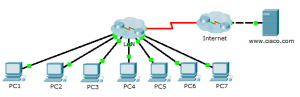
Topology

8.1.1.8 Packet Tracer – Troubleshooting Challenge – Documenting The Network
Addressing Table
| Device | Interface | IP Address | Subnet Mask | Default Gateway |
| PC1 | NIC | 10.2.15.10 | 255.255.255.0 | 10.2.15.1 |
| PC2 | NIC | 10.2.25.10 | 255.255.255.0 | 10.2.25.1 |
| PC3 | NIC | 10.2.35.10 | 255.255.255.0 | 10.2.35.1 |
| PC4 | NIC | 10.3.100.4 | 255.255.255.0 | 10.3.100.1 |
| PC5 | NIC | 10.3.100.5 | 255.255.255.0 | 10.3.100.1 |
| PC6 | NIC | 10.4.1.10 | 255.255.255.0 | 10.4.1.1 |
| PC7 | NIC | 10.5.1.10 | 255.255.255.0 | 10.5.1.1 |
| DNS Server | NIC | 10.1.100.2 | 255.255.255.0 | 10.1.100.1 |
| R1 | S0/0/0 | 10.1.0.4 | 255.255.255.248 | N/A |
| R1 | G0/0 | 10.4.1.1 | 255.255.255.0 | N/A |
| R2 | S0/0/0 | 10.1.0.3 | 255.255.255.248 | N/A |
| R2 | G0/0.100 | 10.3.100.1 | 255.255.255.0 | N/A |
| R2 | G0/0.105 | 10.3.105.1 | 255.255.255.0 | N/A |
| R3 | S0/0/0 | 10.1.0.2 | 255.255.255.248 | N/A |
| R3 | G0/0.5 | 10.2.5.1 | 255.255.255.0 | N/A |
| R3 | G0/0.15 | 10.2.15.1 | 255.255.255.0 | N/A |
| R3 | G0/0.25 | 10.2.25.1 | 255.255.255.0 | N/A |
| R3 | G0/0.35 | 10.2.35.1 | 255.255.255.0 | N/A |
| R4 | S0/0/0 | 10.1.0.5 | 255.255.255.248 | N/A |
| R4 | G0/0 | 10.5.1.1 | 255.255.255.0 | N/A |
| R5 | S0/0/0 | 10.1.0.1 | 255.255.255.248 | N/A |
| R5 | S0/0/1 | 209.165.201.2 | 255.255.255.252 | N/A |
| R5 | G0/0 | 10.1.100.1 | 255.255.255.0 | N/A |
| S1 | None | None | None | None |
| S2 | VLAN 105 | 10.3.105.21 | 255.255.255.0 | 10.3.105.1 |
| S3 | VLAN 105 | 10.3.105.22 | 255.255.255.0 | 10.3.105.1 |
| S4 | VLAN 5 | 10.2.5.21 | 255.255.255.0 | 10.2.5.1 |
| S5 | VLAN 5 | 10.2.5.23 | 255.255.255.0 | 10.2.5.1 |
| S6 | VLAN 5 | 10.2.5.22 | 255.255.255.0 | 10.2.5.1 |
| S7 | None | None | None | None |
Objectives
Part 1: Test Connectivity
Part 2: Discover PC Configuration Information
Part 3: Discover the Configuration Information of the Default Gateway
Part 4: Discover Routes and Neighbors in the Network
Part 5: Draw the Network Topology
Background / Scenario
This activity covers the steps to take to discover a network using primarily the Telnet, show cdp neighbors detail, and show ip route commands. This is Part I of a two-part activity. Part II is Packet Tracer – Troubleshooting Challenge – Using Documentation to Solve Issues.
The topology you see when you open the Packet Tracer activity does not reveal all of the details of the network. The details have been hidden using the cluster function of Packet Tracer. The network infrastructure has been collapsed, and the topology in the file shows only the end devices. Your task is to use your knowledge of networking and discovery commands to learn about the full network topology and document it.
Part 1: Test Connectivity
Packet Tracer needs a little time to converge the network. Ping between the PCs and the www.cisco.com server to verify convergence and to test the network. All PCs should be able to ping one another as well as the server. Remember it may take a few pings before they are successful.
Part 2: Discover PC Configuration Information
Step 1: Access the PC1 command prompt.
Click PC1, the Desktop tab, and then Command Prompt.
Step 2: Determine the addressing information for PC1.
To determine the current IP addressing configuration, enter the ipconfig /all command.
Note: In Packet Tracer, you must enter a space between ipconfig and /all.
Step 3: Document the information for PC1 in the addressing table.
PC> ipconfig /all
FastEthernet0 Connection:(default port)
Physical Address................: 0001.97DA.E057
Link-local IPv6 Address.........: FE80::201:97FF:FEDA:E057
IP Address......................: 10.2.15.10
Subnet Mask.....................: 255.255.255.0
Default Gateway.................: 10.2.15.1
DNS Servers.....................: 10.1.100.2
DHCP Servers....................: 0.0.0.0
Step 4: Repeat Steps 1 to 3 for PCs 2 to 7.
Part 3: Discover the Configuration Information of the Default Gateway
Step 1: Test connectivity between PC1 and its default gateway.
From PC1, ping the default gateway to ensure that you have connectivity.
Step 2: Telnet to the default gateway.
Use the telnet ip-address command. The IP address is that of the default gateway. When prompted for the password, type cisco.
Step 3: View current interface configurations.
- Use both the show ip interface brief and show protocols command to determine the current interface configurations.
- Document the subnet mask information from the show protocols command.
Step 4: Document the hostname and interface configuration of the PC1 gateway router in the addressing table.
Part 4: Discover Routes and Neighbors in the Network
Step 1: On the gateway router for PC1, display the routing table.
- Display the routing table with the show ip route command. You should see five connected routes and six routes learned through EIGRIP, one of which is a default route.
- In addition to the routes, record any other useful information that the routing table provides to help you further discover and document the network.
- Determine if there are more IP addresses you can Telnet to continue discovering the network.
Step 2: Discover directly connected Cisco devices.
On the gateway router for PC1, use the show cdp neighbors detail command to discover other directly connected Cisco devices.
Step 3: Document the neighbor information and test connectivity.
The show cdp neighbors detail command lists information for one neighbor, including its IP address. Document the hostname and IP address of the neighbor, and then ping the IP address to test connectivity. The first two or three pings fail while ARP resolves the MAC address.
Step 4: Telnet to the neighbor and discover directly connected Cisco devices.
- Telnet to the neighbor and use the show cdp neighbors detail command to discover other directly connected Cisco devices.
- You should see three devices listed this time. The PC1 gateway router may be listed for each subinterface.
Note: Use the show interfaces command on the switches to determine the subnet mask information.
Step 5: Document the hostnames and IP addresses of the neighbors and test connectivity.
Document and ping the new neighbors you have discovered. Remember, the first two or three pings fail while ARP resolves MAC addresses.
Step 6: Telnet to each neighbor and check for additional Cisco devices.
Telnet to each of the new neighbors you have discovered, and use the show cdp neighbors detail command to check for any additional Cisco devices. The access password is cisco.
Step 7: Continue discovering and documenting the network.
Exit the Telnet sessions to return to the default gateway router for PC1. From this router, Telnet to other devices in the network to continue discovering and documenting the network. Remember to use the show ip route and show cdp neighbors commands to discover IP addresses you can use for Telnet.
Note: Use the show interfaces command on the switches to determine the subnet mask information.
Step 8: Repeat Steps 1 to 7 as necessary to discover the entire network topology.
Part 5: Draw the Network Topology
Step 1: Draw a topology.
Now that you have discovered all the network devices and documented their addresses, use the Addressing Table information to draw a topology.
Hint: There is a Frame Relay cloud in the middle of the network.
Step 2: Keep this documentation.
- Show your topology diagram and Addressing Table to the Answer for verification.
- Your topology diagram and Addressing Table are needed for Part II of this activity.
Suggested Scoring Rubric
| Activity Section | Question Location | Possible Points | Earned Points |
| Part 5: Draw the Network Topology | Step 2-a | 100 | |
| Part 5 Total | 100 | ||
| Packet Tracer Score | 0 | ||
| Total Score | 100 | ||
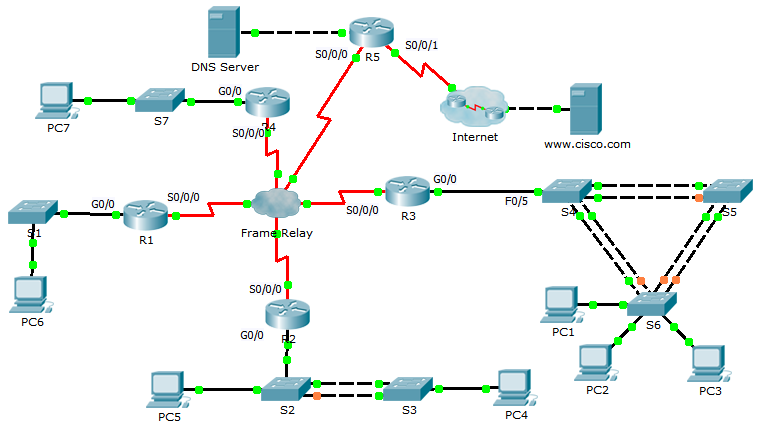
Topology Answer
This topology is a screenshot from the answer network in the PKA. The student’s topology can look quite different, but the connections should all be the same. A good class exercise is to have the students compare their correct topology diagrams to see the benefits and limitations of different layouts. This will also help them to understand that there can be many excellent ways to represent the same network.
Device Configs
Router R1
R1#sh run
no service timestamps log datetime msec
no service timestamps debug datetime msec
no service password-encryption
hostname R1
enable secret class
spanning-tree mode pvst
interface Gig0/0
ip address 10.4.1.1 255.255.255.0
duplex auto
speed auto
interface Gig0/1
no ip address
duplex auto
speed auto
shutdown
interface Serial0/0/0
ip address 10.1.0.4 255.255.255.248
encapsulation frame-relay
interface Serial0/0/1
no ip address
shutdown
interface Vlan1
no ip address
shutdown
router eigrp 1
passive-interface Gig0/0
network 10.0.0.0
no auto-summary
ip classless
line con 0
password cisco
login
line aux 0
line vty 0 4
password cisco
login
end
Router R2
R2#sh run
no service timestamps log datetime msec
no service timestamps debug datetime msec
no service password-encryption
hostname R2
enable secret class
spanning-tree mode pvst
interface GigabitEthernet0/0
no ip address
duplex auto
speed auto
interface GigabitEthernet0/0.100
encapsulation dot1Q 100
ip address 10.3.100.1 255.255.255.0
interface GigabitEthernet0/0.105
encapsulation dot1Q 105 native
ip address 10.3.105.1 255.255.255.0
interface GigabitEthernet0/1
no ip address
duplex auto
speed auto
shutdown
interface Serial0/0/0
ip address 10.1.0.3 255.255.255.248
encapsulation frame-relay
interface Serial0/0/1
no ip address
shutdown
interface Vlan1
no ip address
shutdown
router eigrp 1
network 10.0.0.0
no auto-summary
ip classless
line con 0
password cisco
login
line aux 0
line vty 0 4
password cisco
login
end
Router R3
R3#sh run
no service timestamps log datetime msec
no service timestamps debug datetime msec
no service password-encryption
hostname R3
enable secret class
spanning-tree mode pvst
interface Gig0/0
no ip address
duplex auto
speed auto
interface Gig0/0.5
encapsulation dot1Q 5 native
ip address 10.2.5.1 255.255.255.0
interface Gig0/0.15
encapsulation dot1Q 15
ip address 10.2.15.1 255.255.255.0
interface Gig0/0.25
encapsulation dot1Q 25
ip address 10.2.25.1 255.255.255.0
interface Gig0/0.35
encapsulation dot1Q 35
ip address 10.2.35.1 255.255.255.0
interface Gig0/1
no ip address
duplex auto
speed auto
shutdown
interface Serial0/0/0
ip address 10.1.0.2 255.255.255.248
encapsulation frame-relay
interface Serial0/0/1
no ip address
shutdown
interface Vlan1
no ip address
shutdown
router eigrp 1
network 10.0.0.0
no auto-summary
ip classless
line con 0
password cisco
login
line aux 0
line vty 0 4
password cisco
login
end
Router R4
R4#sh run
no service timestamps log datetime msec
no service timestamps debug datetime msec
no service password-encryption
hostname R4
enable secret class
spanning-tree mode pvst
interface Gig0/0
ip address 10.5.1.1 255.255.255.0
duplex auto
speed auto
interface Gig0/1
no ip address
duplex auto
speed auto
shutdown
interface Serial0/0/0
ip address 10.1.0.5 255.255.255.248
encapsulation frame-relay
interface Serial0/0/1
no ip address
shutdown
interface Vlan1
no ip address
shutdown
router eigrp 1
passive-interface Gig0/0
network 10.0.0.0
no auto-summary
ip classless
line con 0
password cisco
login
line aux 0
line vty 0 4
password cisco
login
end
Router R5
R5#sh run
no service timestamps log datetime msec
no service timestamps debug datetime msec
no service password-encryption
hostname R5
enable secret class
spanning-tree mode pvst
interface Gig0/0
ip address 10.1.100.1 255.255.255.0
duplex auto
speed auto
interface Gig0/1
no ip address
duplex auto
speed auto
shutdown
interface Serial0/0/0
ip address 10.1.0.1 255.255.255.248
encapsulation frame-relay
ip nat inside
interface Serial0/0/1
ip address 209.165.201.2 255.255.255.252
ip nat outside
no cdp enable
interface Vlan1
no ip address
shutdown
router eigrp 1
passive-interface Gig0/0
passive-interface Serial0/0/1
network 10.0.0.0
default-information originate
no auto-summary
ip nat pool LAN 209.165.202.128 209.165.202.159 netmask 255.255.255.224
ip nat inside source list 1 pool LAN overload
ip classless
ip route 0.0.0.0 0.0.0.0 Serial0/0/1
access-list 1 permit 10.0.0.0 0.255.255.255
line con 0
password cisco
login
line aux 0
line vty 0 4
password cisco
login
end
Router ISP
ISP#sh run
no service timestamps log datetime msec
no service timestamps debug datetime msec
no service password-encryption
hostname ISP
spanning-tree mode pvst
interface Gig0/0
ip address 209.165.200.225 255.255.255.252
duplex auto
speed auto
interface Gig0/1
no ip address
duplex auto
speed auto
shutdown
interface Serial0/0/0
ip address 209.165.201.1 255.255.255.252
clock rate 64000
interface Serial0/0/1
no ip address
interface Serial0/2/0
no ip address
interface Serial0/2/1
no ip address
interface Vlan1
no ip address
shutdown
ip classless
ip route 209.165.202.128 255.255.255.224 Serial0/0/0
no cdp run
line con 0
line aux 0
line vty 0 4
login
end
Switch S1
S1#sh run
hostname S1
enable secret class
spanning-tree mode pvst
interface FastEthernet0/1
interface FastEthernet0/2
interface FastEthernet0/3
interface FastEthernet0/4
interface FastEthernet0/5
interface FastEthernet0/6
interface FastEthernet0/7
interface FastEthernet0/8
interface FastEthernet0/9
interface FastEthernet0/10
interface FastEthernet0/11
interface FastEthernet0/12
interface FastEthernet0/13
interface FastEthernet0/14
interface FastEthernet0/15
interface FastEthernet0/16
interface FastEthernet0/17
interface FastEthernet0/18
interface FastEthernet0/19
interface FastEthernet0/20
interface FastEthernet0/21
interface FastEthernet0/22
interface FastEthernet0/23
interface FastEthernet0/24
interface GigabitEthernet1/1
interface GigabitEthernet1/2
interface Vlan1
no ip address
shutdown
line con 0
password cisco
login
line vty 0 4
password cisco
login
line vty 5 15
login
end
Switch S2
S2#sh run
no service timestamps log datetime msec
no service timestamps debug datetime msec
no service password-encryption
hostname S2
enable secret class
spanning-tree mode pvst
interface FastEthernet0/1
switchport trunk native vlan 105
switchport mode trunk
interface FastEthernet0/2
switchport trunk native vlan 105
switchport mode trunk
interface FastEthernet0/3
switchport trunk native vlan 105
switchport mode trunk
interface FastEthernet0/4
interface FastEthernet0/5
switchport access vlan 100
switchport mode access
interface FastEthernet0/6
interface FastEthernet0/7
interface FastEthernet0/8
interface FastEthernet0/9
interface FastEthernet0/10
interface FastEthernet0/11
interface FastEthernet0/12
interface FastEthernet0/13
interface FastEthernet0/14
interface FastEthernet0/15
interface FastEthernet0/16
interface FastEthernet0/17
interface FastEthernet0/18
interface FastEthernet0/19
interface FastEthernet0/20
interface FastEthernet0/21
interface FastEthernet0/22
interface FastEthernet0/23
interface FastEthernet0/24
interface GigabitEthernet1/1
interface GigabitEthernet1/2
interface Vlan1
no ip address
shutdown
interface Vlan105
ip address 10.3.105.21 255.255.255.0
line con 0
password cisco
login
line vty 0 4
password cisco
login
line vty 5 15
login
end
Switch S3
S3#sh run
no service timestamps log datetime msec
no service timestamps debug datetime msec
no service password-encryption
hostname S3
enable secret class
spanning-tree mode pvst
interface FastEthernet0/1
interface FastEthernet0/2
switchport trunk native vlan 105
switchport mode trunk
interface FastEthernet0/3
switchport trunk native vlan 105
switchport mode trunk
interface FastEthernet0/4
interface FastEthernet0/5
interface FastEthernet0/6
interface FastEthernet0/7
interface FastEthernet0/8
interface FastEthernet0/9
interface FastEthernet0/10
switchport access vlan 100
switchport mode access
interface FastEthernet0/11
interface FastEthernet0/12
interface FastEthernet0/13
interface FastEthernet0/14
interface FastEthernet0/15
interface FastEthernet0/16
interface FastEthernet0/17
interface FastEthernet0/18
interface FastEthernet0/19
interface FastEthernet0/20
interface FastEthernet0/21
interface FastEthernet0/22
interface FastEthernet0/23
interface FastEthernet0/24
interface GigabitEthernet1/1
interface GigabitEthernet1/2
interface Vlan1
no ip address
shutdown
interface Vlan105
ip address 10.3.105.22 255.255.255.0
ip default-gateway 10.3.1.1
line con 0
password cisco
login
line vty 0 4
password cisco
login
line vty 5 15
login
end
Switch S4
S4#sh run
no service timestamps log datetime msec
no service timestamps debug datetime msec
no service password-encryption
hostname S4
enable secret class
spanning-tree mode pvst
spanning-tree vlan 1,5,15,25,35 priority 4096
interface FastEthernet0/1
switchport trunk native vlan 5
switchport mode trunk
interface FastEthernet0/2
switchport trunk native vlan 5
switchport mode trunk
interface FastEthernet0/3
switchport trunk native vlan 5
switchport mode trunk
interface FastEthernet0/4
switchport trunk native vlan 5
switchport mode trunk
interface FastEthernet0/5
switchport trunk native vlan 5
switchport mode trunk
interface FastEthernet0/6
interface FastEthernet0/7
interface FastEthernet0/8
interface FastEthernet0/9
interface FastEthernet0/10
interface FastEthernet0/11
interface FastEthernet0/12
interface FastEthernet0/13
interface FastEthernet0/14
interface FastEthernet0/15
interface FastEthernet0/16
interface FastEthernet0/17
interface FastEthernet0/18
interface FastEthernet0/19
interface FastEthernet0/20
interface FastEthernet0/21
interface FastEthernet0/22
interface FastEthernet0/23
interface FastEthernet0/24
interface GigabitEthernet1/1
interface GigabitEthernet1/2
interface Vlan1
no ip address
shutdown
interface Vlan5
ip address 10.2.5.21 255.255.255.0
ip default-gateway 10.2.5.1
line con 0
password cisco
login
line vty 0 4
password cisco
login
line vty 5 15
login
end
Switch S5
S5#sh run
no service timestamps log datetime msec
no service timestamps debug datetime msec
no service password-encryption
hostname S5
enable secret class
spanning-tree mode pvst
interface FastEthernet0/1
switchport trunk native vlan 5
switchport mode trunk
interface FastEthernet0/2
switchport trunk native vlan 5
switchport mode trunk
interface FastEthernet0/3
switchport trunk native vlan 5
switchport mode trunk
interface FastEthernet0/4
switchport trunk native vlan 5
switchport mode trunk
interface FastEthernet0/5
interface FastEthernet0/6
interface FastEthernet0/7
interface FastEthernet0/8
interface FastEthernet0/9
interface FastEthernet0/10
interface FastEthernet0/11
interface FastEthernet0/12
interface FastEthernet0/13
interface FastEthernet0/14
interface FastEthernet0/15
interface FastEthernet0/16
interface FastEthernet0/17
interface FastEthernet0/18
interface FastEthernet0/19
interface FastEthernet0/20
interface FastEthernet0/21
interface FastEthernet0/22
interface FastEthernet0/23
interface FastEthernet0/24
interface GigabitEthernet1/1
interface GigabitEthernet1/2
interface Vlan1
no ip address
shutdown
interface Vlan5
ip address 10.2.5.23 255.255.255.0
ip default-gateway 10.2.5.1
line con 0
password cisco
login
line vty 0 4
password cisco
login
line vty 5 15
login
end
Switch S6
S6#sh run
no service timestamps log datetime msec
no service timestamps debug datetime msec
no service password-encryption
hostname S6
enable secret class
spanning-tree mode pvst
interface FastEthernet0/1
switchport trunk native vlan 5
switchport mode trunk
interface FastEthernet0/2
switchport trunk native vlan 5
switchport mode trunk
interface FastEthernet0/3
switchport trunk native vlan 5
switchport mode trunk
interface FastEthernet0/4
switchport trunk native vlan 5
switchport mode trunk
interface FastEthernet0/5
interface FastEthernet0/6
switchport access vlan 15
switchport mode access
interface FastEthernet0/7
interface FastEthernet0/8
interface FastEthernet0/9
interface FastEthernet0/10
interface FastEthernet0/11
switchport access vlan 25
switchport mode access
interface FastEthernet0/12
interface FastEthernet0/13
interface FastEthernet0/14
interface FastEthernet0/15
interface FastEthernet0/16
switchport access vlan 35
switchport mode access
interface FastEthernet0/17
interface FastEthernet0/18
interface FastEthernet0/19
interface FastEthernet0/20
interface FastEthernet0/21
interface FastEthernet0/22
interface FastEthernet0/23
interface FastEthernet0/24
interface GigabitEthernet1/1
interface GigabitEthernet1/2
interface Vlan1
no ip address
shutdown
interface Vlan5
ip address 10.2.5.22 255.255.255.0
ip default-gateway 10.2.5.1
line con 0
password cisco
login
line vty 0 4
password cisco
login
line vty 5 15
login
end
Switch S7
S7#sh run
no service timestamps log datetime msec
no service timestamps debug datetime msec
no service password-encryption
hostname S7
enable secret class
spanning-tree mode pvst
interface FastEthernet0/1
interface FastEthernet0/2
interface FastEthernet0/3
interface FastEthernet0/4
interface FastEthernet0/5
interface FastEthernet0/6
interface FastEthernet0/7
interface FastEthernet0/8
interface FastEthernet0/9
interface FastEthernet0/10
interface FastEthernet0/11
interface FastEthernet0/12
interface FastEthernet0/13
interface FastEthernet0/14
interface FastEthernet0/15
interface FastEthernet0/16
interface FastEthernet0/17
interface FastEthernet0/18
interface FastEthernet0/19
interface FastEthernet0/20
interface FastEthernet0/21
interface FastEthernet0/22
interface FastEthernet0/23
interface FastEthernet0/24
interface GigabitEthernet1/1
interface GigabitEthernet1/2
interface Vlan1
no ip address
shutdown
line con 0
line vty 0 4
login
line vty 5 15
login
end
From year to year, Cisco has updated many versions with difference questions. The latest version is version 6.0 in 2018. What is your version? It depends on your instructor creating your class. We recommend you to go thought all version if you are not clear. While you take online test with netacad.com, You may get random questions from all version. Each version have 1 to 10 different questions or more. After you review all questions, You should practice with our online test system by go to "Online Test" link below.