Last Updated on March 23, 2018 by Admin
1.3.2.5 Packet Tracer – Investigating Directly Connected Routes
From year to year, Cisco has updated many versions with difference questions. The latest version is version 6.0 in 2018. What is your version? It depends on your instructor creating your class. We recommend you to go thought all version if you are not clear. While you take online test with netacad.com, You may get random questions from all version. Each version have 1 to 10 different questions or more. After you review all questions, You should practice with our online test system by go to "Online Test" link below.
Packet Tracer – Investigating Directly Connected Routes (Answer Version)
Answer Note: Red font color or Gray highlights indicate text that appears in the Answer copy only.
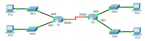
Topology

1.3.2.5 Packet Tracer – Investigating Directly Connected Routes
Objectives
Part 1: Investigate IPv4 Directly Connected Routes
Part 2: Investigate IPv6 Directly Connected Routes
Background
The network in the activity is already configured. You will log in to the routers and use show commands to discover and answer the questions below about the directly connected routes.
Note: The user EXEC password is cisco and the privileged exec password is class.
Part 1: Investigate IPv4 Directly Connected Routes
Step 1: Use show commands to gather information about the IPv4 directly connected networks.
Enter the following command on R1:
R1> show ip route ?
- What option would be most beneficial in determining the networks assigned to the interfaces of the router? connected
- Which networks are directly connected on R1? Hint: Use the option determined above.
- C 172.31.20.0/23 is directly connected, GigabitEthernet0/0
- C 172.31.22.0/23 is directly connected, GigabitEthernet0/1
- C 209.165.200.224/30 is directly connected, Serial0/0/0
- Which IP addresses are assigned to the LAN interfaces on R1?
- Interface IP-Address OK? Method Status Protocol
- GigabitEthernet0/0 172.31.21.254 YES manual up up
- GigabitEthernet0/1 172.31.23.254 YES manual up up
- Which networks are directly connected on R2?
- C 172.31.24.0/24 is directly connected, GigabitEthernet0/0
- C 172.31.25.0/24 is directly connected, GigabitEthernet0/1
- C 209.165.200.224/30 is directly connected, Serial0/0/0
- Which IP addresses are assigned to the LAN interfaces on R2?
- Interface IP-Address OK? Method Status Protocol
- GigabitEthernet0/0 172.31.24.254 YES manual up up
- GigabitEthernet0/1 172.31.25.254 YES manual up up
Step 2: Verify PC addressing and test connectivity.
- Open a command prompt on PC1. Issue the command to display the IP settings. Based on the output, would you expect PC1 to be able to communicate with all interfaces on the router? Provide a short answer describing your expectations. The PC has the correct gateway address and the router lists all of the connected networks in the routing table.
- Open a command prompt on PC2. Issue the command to display the IP settings. Based on the output, would you expect PC2 to be able to communicate with PC1? Verify your expectations. Ping is successful
- Determine the IP addresses of PC3 and PC4. Record the results and determine if PC3 and PC4 are able to communicate. PC3 – IP address 172.31.24.10, PC4 – IP address 172.31.25.10
- Test connectivity from PC1 to PC3. Was the test successful? yes
- Bonus: Looking at the outputs of the routing tables on R1 and R2, what might indicate a reason for the success or failure of communication between PC1 and PC3? The default static route 0.0.0.0/0
Part 2: Investigate IPv6 Directly Connected Routes
Step 1: Use show commands to gather information about the IPv6 directly connected networks.
- Which IPv6 networks are available on R1?
- C 2001:DB8:C001:1::/64 [0/0]
- via ::, GigabitEthernet0/0
- L 2001:DB8:C001:1::1/128 [0/0]
- via ::, GigabitEthernet0/0
- C 2001:DB8:C001:2::/64 [0/0]
- via ::, GigabitEthernet0/1
- L 2001:DB8:C001:2::1/128 [0/0]
- via ::, GigabitEthernet0/1
- C 2001:DB8:C001:ACE::/64 [0/0]
- via ::, Serial0/0/0L 2001:DB8:C001:ACE::1/128 [0/0]
- via ::, Serial0/0/0
- Which IPv6 unicast addresses are assigned to the LAN interfaces on R1?
- L 2001:DB8:C001:1::1/128 [0/0]
- via ::, GigabitEthernet0/0
- L 2001:DB8:C001:2::1/128 [0/0]
- via ::, GigabitEthernet0/1
- Which IPv6 networks are available on R2?
- C 2001:DB8:C001:3::/64 [0/0]
- via ::, GigabitEthernet0/0
- L 2001:DB8:C001:3::1/128 [0/0]
- via ::, GigabitEthernet0/0
- C 2001:DB8:C001:4::/64 [0/0]
- via ::, GigabitEthernet0/1
- L 2001:DB8:C001:4::1/128 [0/0]
- via ::, GigabitEthernet0/1
- C 2001:DB8:C001:ACE::/64 [0/0]
- via ::, Serial0/0/0
- L 2001:DB8:C001:ACE::2/128 [0/0]
- via ::, Serial0/0/0
- Which IPv6 addresses are assigned to the LAN interfaces on R2?
- L 2001:DB8:C001:3::1/128 [0/0]
- via ::, GigabitEthernet0/0
- L 2001:DB8:C001:4::1/128 [0/0]
- via ::, GigabitEthernet0/1
Step 2: Verify PC settings and connectivity.
- Open a command prompt on PC1. Issue the command to display the IPv6 settings. Based on the output, would you expect PC1 to be able to communicate with all interfaces on the router? Provide a short answer describing your expectations. The PC has the correct gateway address using the link local address on the router and the router lists all of the connected networks in the routing table.
- Open a command prompt on PC2. Issue the command to display the IPv6 settings. Based on the output, would you expect PC2 to be able to communicate with PC1? Verify your expectations. Ping is successful
- Determine the IPv6 addresses of PC3 and PC4. Record the results and determine if PC3 and PC4 are able to communicate. PC3 – IP address 2001:DB8:C001:3::10/64, PC4 – IP address 2001:DB8:C001: 4::10/64
- Test connectivity from PC1 to PC3. Was the test successful? yes
- Bonus: What might indicate a reason for the success or failure of communication between PC1 and PC3 after looking at the outputs of the IPv6 routing tables on R1 and R2? The default IPv6 static route
- S ::/0 [1/0]
- via ::, Serial0/0/0
From year to year, Cisco has updated many versions with difference questions. The latest version is version 6.0 in 2018. What is your version? It depends on your instructor creating your class. We recommend you to go thought all version if you are not clear. While you take online test with netacad.com, You may get random questions from all version. Each version have 1 to 10 different questions or more. After you review all questions, You should practice with our online test system by go to "Online Test" link below.
Suggested Scoring Rubric
| Activity Section | Question Location | Possible Points | Earned Points |
| Part 1: Investigate IPv4 Directly Connected Routes | Step 1 | 25 | |
| Step 2 | 25 | ||
| Part 2: Investigate IPv6 Directly Connected Routes | Step 1 | 25 | |
| Step 2 | 25 | ||
| Total Score | 100 | ||