Last Updated on February 10, 2019 by Admin
9.3.2.2 Lab – Troubleshooting Physical Connectivity Answers
Lab – Troubleshooting Physical Connectivity (Answers Version)
Answers Note: Red font color or gray highlights indicate text that appears in the Answers copy only.
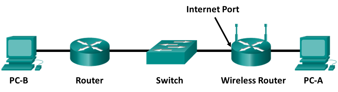
Topology
Objectives
- Examine device LEDs to determine proper Ethernet connectivity.
- Select the correct Ethernet cable for use between various types of devices.
- Visually inspect cables for potential problems.
- Use a cable tester to help identify cabling problems.
Background / Scenario
Physical cabling is one of the most common sources of network problems. This lab focuses on connectivity issues related to network cabling. You will visually inspect cabling and LED link lights to evaluate physical connections and to determine if the correct type of cable is being used based on the devices they interconnect. You will also use a cable tester to identify problems with cables.
The Answers will set up the network topology similar to the one shown and will preconfigure the hosts and network devices. The Answers will introduce various connectivity problems, and you will diagnose the cause of these problems by inspecting link lights and testing cables between devices. Various cable types, both good and bad, will be used to interconnect devices for each scenario in the lab.
Work in teams of two, with each person taking the lead in half of the problem scenarios.
This lab requires setup by the Answers to create various connectivity problems, mainly by using an incorrect cable type (straight-through or crossover) or using a defective cable (miswired or improperly terminated). The focus is on link connectivity and cable testing.
The wireless router is both a DHCP client and server. The external router is configured as a DHCP server to give the wireless router client the required IP configuration. PC-B has a static IP configuration. Students have access to the command line on PC-A, but not to the wireless router, router, or PC-B command-line interface (CLI) or GUI. They have visual access to all network interface cards, device interfaces, and ports.
The focus of this lab is on physical connectivity problems. No software configuration problems are introduced. End-to-end connectivity is tested by pinging from PC-A to PC-B.
Cabling Problem Scenarios:
Incorrect cable type between PC-A and wireless router (crossover instead of a straight-through)
Miswired cable between switch and router (incorrect pinouts – send/receive to pins other than 1, 2, 3, or 6)
Incorrect cable type between Router and PC-B (straight-through instead of a crossover)
Improperly terminated cable between wireless router and Switch (open on wires to pins 1, 2, 3, or 6 at RJ-45 connector)
Required Resources
- 2 PCs running Windows 10
- Wireless router configured as a DHCP server and client (default configuration)
- Router with two Ethernet interfaces, such as Cisco 1941, configured as the DHCP server to wireless router (preconfigured)
- Switch, such as Cisco 2960
- Mix of Ethernet Cat-5 (minimum) straight-through and crossover cabling, both good and bad, to connect hosts and network devices
- Basic Cat-5 Ethernet cable tester (RJ-45 pin-to-pin continuity checker)
- Advanced cable tester (optional)
Step 1: Build the network and configure the hosts.
- Ask your Answers to set up a network topology similar to the one shown with a preconfigured PC-A and PC-B client computers, wireless router, Switch, and Router. Initially, correct and properly functioning cabling is used so that end-to-end connectivity can be verified. The Answers then introduces cabling problems in each scenario.
- Problems can consist of using the wrong type of cable between two devices (straight-through or crossover) or using a defective cable (miswired or improperly terminated). Observe device interface link lights, visually inspect cables, and use a cable tester to determine the problems.
- Complete steps 2 and 3 of this lab before the Answers introduces problems.
Step 2: Record the correct cable types used between devices.
Refer to the topology diagram and record the cable type that should be used (straight-through or crossover) based on the devices being connected. Ask your Answers verify this information before proceeding.
Which type of cable should be used from PC-A to wireless router?____________________
Straight-through cable
Which type of cable should be used from the Internet port of the wireless router to Switch?____________
Straight-through cable
Which type of cable should be used from Switch to Router?__________________
Straight-through cable
Which type of cable should be used from Router to PC-B?___________________
Crossover cable
Step 3: Record the IP address information for the computers.
- Use the ipconfig command, or get the IP address of PC-A from your Answers, and record it here.
PC-A IP address:__________________ Answers will vary – DHCP 192.168.1.x
Get the PC-B IP address from your Answers and record it here.
PC-B IP address: __________________Answers will vary – Static set by Answers - Before starting on problem scenarios, verify end-to-end connectivity by pinging from PC-A to PC-B. If you do not get a reply from PC-B, check with your Answers. There may be a problem with the initial hardware or software setup.
Step 4: Scenario 1
- After your Answers sets up the problem, use visual inspection and a cable tester to isolate the problem.
- Ping from PC-A to PC-B. What happened?____________________________________________________________________________________
PC-A is unable to reach destination host (PC-B). - Check the LED link lights on the various device interfaces. Write down any that are not lit.
____________________________________________________________________________________
PC-A NIC LED and LED on front of wireless router that corresponds to the port where PC-A is connected. - Disconnect and inspect the cable connecting the network interfaces that were not lit. Describe the problem and how you were able to identify it.
____________________________________________________________________________________________________________________________________________________________________________________________________________________________________________________________
Problem: Incorrect cable type between PC-A and wireless router (Crossover instead of a straight-through)
Visual inspection could reveal an incorrect cable type based on those identified in Step 2. A basic cable tester would show that wire continuity was good but that this is a crossover cable. A straight-through cable should be used for connecting a host to a switch.
What did you do to correct the problem?____________________________________________________________________________________
Replaced the crossover cable with a straight-through cable. - When the problem is corrected, retest and verify end-to-end connectivity by pinging from PC-A to PC-B. Was the ping successful?_________________Yes
Step 5: Scenario 2
- After your Answers sets up the problem, use visual inspection and a cable tester to isolate the problem.
- Ping from PC-A to PC-B. What happened?____________________________________________________________________________________
PC-A is unable to reach destination host (PC-B) - Check the LED link lights on the various device interfaces. Write down any that are not lit.
____________________________________________________________________________________
Router Ethernet interface link LED, and LED on PC-B NIC. - Disconnect and inspect the cable connecting the network interfaces that were not lit. Describe the problem and how you were able to identify it.
____________________________________________________________________________________________________________________________________________________________________________________________________________________________________________________________ - What did you do to correct the problem?____________________________________________________________________________________
- When the problem is corrected, retest and verify end-to-end connectivity by pinging from PC-A to PC-B. Was the ping successful?__________________ Yes