Last Updated on February 3, 2019 by Admin
8.5.1.3 Packet Tracer – Implementing Basic Connectivity Answers
Packet Tracer – Implement Basic Connectivity (Answers Version)
Answers Note: Red font color or gray highlights indicate text that appears in the Answers copy only.
Topology
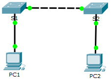
Addressing Table
| Device | Interface | IP Address | Subnet Mask |
| S1 | VLAN 1 | 192.168.1.253 | 255.255.255.0 |
| S2 | VLAN 1 | 192.168.1.254 | 255.255.255.0 |
| PC1 | NIC | 192.168.1.1 | 255.255.255.0 |
| PC2 | NIC | 192.168.1.2 | 255.255.255.0 |
Objectives
Part 1: Perform a Basic Configuration on S1 and S2
Part 2: Configure the PCs
Part 3: Configure the Switch Management Interface
Background
In this activity, you will first perform basic switch configurations. Then you will implement basic connectivity by configuring IP addressing on the switches and PCs. When the IP addressing configuration is complete, you will use various show commands to verify configurations and use the ping command to verify basic connectivity between devices.
Part 1: Perform a Basic Configuration on S1 and S2
Step 1: Configure S1 with a hostname.
- Click S1, and then click the CLI tab.
- Enter the privileged EXEC mode. Then enter the global configuration mode.
Switch> enable
Switch# configure terminal
Enter configuration commands, one per line. End with CNTL/Z. - Configure the hostname as S1.
Switch(config)# hostname S1
S1(config)#
Step 2: Configure the console and privileged EXEC mode passwords.
- Configure cisco as the console password and enable login.
S1(config)# line console 0
S1(config-line)# password ciscoS1(config-line)# login
S1(config-line)# exit - Use class for the encrypted privileged EXEC mode password.
S1(config)# enable secret class
Step 3: Verify the password configurations for S1.
- To verify that the passwords were configured correctly, enter end to exit the global configuration mode. Type exit to exit the privileged EXEC mode.
S1(config)# end
S1#
%SYS-5-CONFIG_I: Configured from console by console
S1# exit - Press Enter and you will be prompted for a password to enter the user EXEC mode.
What password did you use? __________________cisco - Type enable to enter the privileged EXEC mode. Enter the password when prompted.
What password did you use?__________________ class - Enter configure terminal to enter global configuration mode.
Step 4: Configure a message of the day (MOTD) banner.
In this step, you will configure a message of the day banner to warn unauthorized access. The following text is an example:
Authorized access only. Violators will be prosecuted to the full extent of the law.
Use the banner motd command with the sample message. You can choose another message.
S1(config)# banner motd “Authorized access only. Violators will be prosecuted to the full extent of the law.”
Step 5: Save the configuration file to NVRAM.
- Exit to privileged EXEC mode.
S1(config)# exit
S1#
%SYS-5-CONFIG_I: Configured from console by console
S1# - Enter the copy running-config startup-config command to save the configuration.
S1# copy running-config startup-config
Destination filename [startup-config]?
Building configuration…
[OK]
Step 6: Repeat Steps 1 through 5 on S2.
Part 2: Configure the PCs
Step 1: Configure both PCs with IP addresses.
- Click PC1, and then click the Desktop tab.
- Click IP Configuration. In the Addressing Table above, you can see that the IP address for PC1 is supposed to be 192.168.1.1 and the subnet mask 255.255.255.0. Enter this information for PC1 in the IP Configuration window.
- Repeat steps 1a and 1b for PC2.
Step 2: Test connectivity to switches.
- Click PC1. Close the IP Configuration window if it is still open. In the Desktop tab, click Command Prompt.
- Type the ping command and the IP address for S1, and press Enter.
Packet Tracer PC Command Line 1.0
PC> ping 192.168.1.253
Were you successful? Explain.
____________________________________________________________________________________
It should not be successful because the switches have not been configured with an IP address.
Part 3: Configure the Switch Management Interface
Step 1: Configure S1 with an IP address.
Switches can be used without any configurations. Switches forward information from one port to another based on Media Access Control (MAC) addresses. Why does a switch need an IP address?
______________________________________________________________________________________________________________________________________________________________________________
An IP address is required to connect to a switch remotely. The switch is managed through VLAN1 by default.
- In the global configuration mode, enter the following commands to configure S1 with an IP address in VLAN 1.
S1# configure terminal
Enter configuration commands, one per line. End with CNTL/Z.
S1(config)# interface vlan 1
S1(config-if)# ip address 192.168.1.253 255.255.255.0
S1(config-if)# no shutdown
%LINEPROTO-5-UPDOWN: Line protocol on Interface Vlan1, changed state to up
S1(config-if)#
S1(config-if)# exit
S1#
What does the no shutdown command?____________________________________________________________________________________
The no shutdown command administratively enables the interface to an active state. - Save the configuration.
S1# copy running-config startup-config
Destination filename [startup-config]?
Building configuration…
[OK]
S1# - Verify the IP address configuration on S1.
S1# show ip interface brief
<output omitted>
Vlan1 192.168.1.253 YES manual up up
Step 2: Configure S2 with an IP address.
Use the information in the addressing table repeat the same process in Step 1 to configure S2 with an IP address. Remember to save and verify your configurations.
Step 3: Verify network connectivity.
Network connectivity can be verified using the ping command. It is very important that connectivity exists throughout the network.
- Click PC1, and then click the Desktop tab.
- Open the Command Prompt.
- Ping the IP address for PC2.
- Ping the IP address for S1.
- Ping the IP address for S2.
- From PC2, ping the other devices in the network.
- From S1, ping the other devices in the network. The ping to PC1 is displayed below as an example.
S1> ping 192.168.1.1
Type escape sequence to abort.
Sending 5, 100-byte ICMP Echos to 192.168.1.1, timeout is 2 seconds:
!!!!!
Success rate is 100 percent (5/5), round-trip min/avg/max = 0/0/1 ms - From S2, ping the other devices in the network.
All pings should be successful. If your first ping result is 80%, retry; it should now be 100%. You will learn why a ping may fail the first time later in your studies. If you are unable to ping any of the devices, check your configuration for errors.
Suggested Scoring Rubric
| Activity Section | Question Location | Possible Points | Earned Points |
| Part 1: Perform a Basic Configuration on S1 and S2 | Step 3b | 2 | |
| Step 3c | 2 | ||
| Part 2: Configure the PCs | Step 2b | 2 | |
| Part 3: Configure the Switch Management Interface | Step 1, q1 | 2 | |
| Step 1, q2 | 2 | ||
| Questions | 10 | ||
| Packet Tracer Score | 90 | ||
| Total Score | 100 | ||