Last Updated on January 28, 2019 by Admin
6.5.1.1 Class Activity – Can You Read This Map Answers
Class Activity – Can You Read This Map? (Answers Version)
Answers Note: Red font color or gray highlights indicate text that appears in the instructor copy only.
Objectives
Explain how network devices use routing tables to direct packets to a destination network.
Background /Scenario
Note: It is suggested that students work in pairs; however, if preferred, students can complete this activity individually.
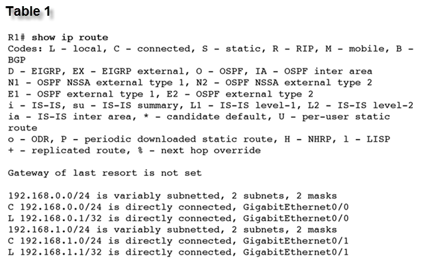
Your instructor will provide you with output generated by a router’s show ip route command. Use Packet Tracer to build a topology model using this routing information.
At a minimum, the following should be used in your topology model:
- 1 Catalyst 2960 switch
- 1 Cisco Series 1941 Router with one HWIC-4ESW switching port modular card and IOS version 15.1 or higher
- 3 PCs (can be servers, generic PCs, laptops, etc.)
Use the note tool in Packet Tracer to indicate the addresses of the router interfaces and possible addresses for the end devices you chose for your model.
Label all end devices, ports, and addresses ascertained from the show ip route output/routing table information in your Packet Tracer file. Save your work in hard or soft copy to share with the class.
Answers Note: This Modeling Activity is not intended to be a graded assignment. Its purpose is to encourage students to reflect on their perceptions of how a network is configured and then checked for routing table information.
Print out or project the Table 1 graphic found in the Required Resources section of this document. Students should be able to assist each other as they read the routing table provided and then construct the model using Packet Tracer software. Facilitation of small group discussion should be initiated as a result of this activity.
Answers Note: It is suggested, but not required, that students work in pairs for this activity.
Required Resources
- Packet Tracer software program.
- Routing Table 1 – students can use the table to assist each other as they read the information provided and then construct the model using Packet Tracer.
Reflection
What was the hardest part of designing this network model? Explain your answer.
______________________________________________________________________________________________________________________________________________________________________________
Answers will vary within groups – some students may mention source or destination identifiers or some may mention the actual IP addresses being cited in the routing table – the important concept here is that students can comfortably identify where information is coming from on the final routing table as depicted.
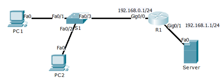
Topologies will vary by group – some students will place their switch off of the Gig0/1 port, etc.
Optional: As an advanced modeling activity, students can create a simple one-router network with four Gigabit interfaces connected to end devices, configure the router and LANs with passwords, IP addresses, banners, etc., and then produce a routing table to support the network information.
Possible topology built by the students could look like this:
Identify elements of the model that map to IT-related content:
- Reading a routing table can verify how a network has been addressed logically.
- A routing table can assist with identifying the physical topology of the network.
- A routing table identifies to the reader which ports are operating and on which networks they are operating