Last Updated on January 28, 2019 by Admin
6.3.2.7 Lab – Exploring Router Physical Characteristics Answers
Lab – Exploring Router Physical Characteristics (Answers Version)
Answers Note: Red font color or gray highlights indicate text that appears in the instructor copy only.
Topology

Objectives
Part 1: Examine Router External Characteristics
Part 2: Examine Router Internal Characteristics Using Show Commands
Background / Scenario
In this lab, you will examine the outside of the router to become familiar with its characteristics and components, such as its power switch, management ports, LAN and WAN interfaces, indicator lights, network expansion slots, memory expansion slots, and USB ports.
You will also identify the internal components and characteristics of the IOS by consoling into the router and issuing various commands, such as show version and show interfaces, from the CLI.
Note: The routers used with CCNA hands-on labs are Cisco 1941 Integrated Services Routers (ISRs) with Cisco IOS Release 15.2(4)M3 (universalk9 image). Other routers and Cisco IOS versions can be used. Depending on the model and Cisco IOS version, the commands available and output produced might vary from what is shown in the labs.
Note: Make sure that the routers have been erased and have no startup configurations. If you are unsure, contact your instructor.
Answers Note: Refer to the Answers Lab Manual for the procedures to initialize and reload devices.
Answers Note: Depending on equipment availability, the instructor may wish to use the lab as a guided lecture/demonstration to point out the router characteristics and discuss them with the class.
Required Resources
- 1 Router (Cisco 1941 with Cisco IOS Release 15.2(4)M3 universal image or comparable)
- 1 PC (Windows 7 or 8 with terminal emulation program, such as Tera Term)
- Console cables to configure the Cisco IOS devices via the console ports
Part 1: Examine Router External Characteristics
Use the images below, as well as your own direct inspection of the backplane of a Cisco router, to answer the following questions. Feel free to draw arrows and circle the areas of the image that correctly identify the parts.
Note: The router depicted in the images below is a Cisco 1941 router, which may be different from the make and model of the routers in your particular academy. You can find device information and specifications for the Cisco 1941 series routers at the Cisco.com website. Additional information, including answers to many of the questions below can be found here:
http://www.cisco.com/en/US/prod/collateral/routers/ps10538/data_sheet_c78_556319.html
Step 1: Identify the various parts of a Cisco router.
The image shown in this step is of the backplane of a Cisco 1941 ISR. Use it to answer the questions in this step. In addition, if you are examining a different model router, a space has been provided here for you to draw the backplane and identify components and interfaces as specified in the questions that follow.
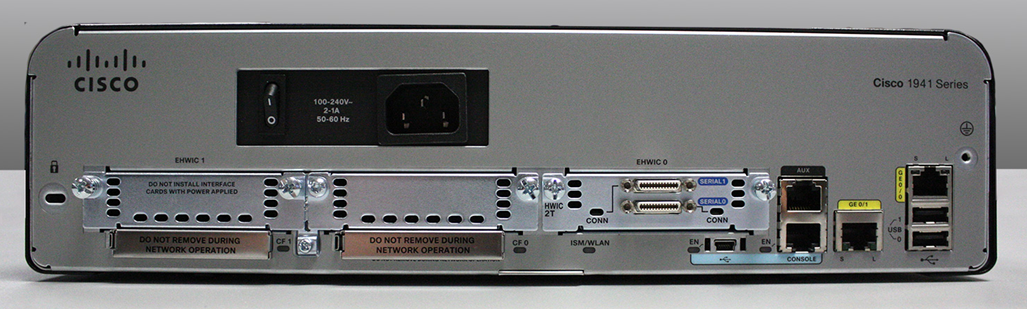
- Circle and label the router’s power switch. Is the power switch on your router in the same area as the router depicted in the image?____________________________________________________________________________________
Answers may vary depending on the academy’s lab routers. Students should draw a line around the on/off switch in the image - Circle and label the management ports. What are the built-in management ports? Are the management ports the same on your router? If not, how are they different?
____________________________________________________________________________________
Answers may vary depending on the academy’s lab routers. Students should draw a circle around the console port, auxiliary port, and mini USB console port in the image. - Circle and label the router’s LAN interfaces. How many LAN interfaces does the router in the image have and what is the interface technology type? Are the LAN interfaces the same on your router? If not, how are they different?____________________________________________________________________________________
Answers may vary depending on the academy’s lab routers. Students should draw a circle around the Gigabit Ethernet 0/0 and 0/1 interfaces in the image. - Circle and label the router’s WAN interfaces. How many WAN interfaces does the router in the image have and what is the interface technology type? Are the WAN interfaces the same on your router? If not, how are they different?____________________________________________________________________________________
Answers may vary depending on the academy’s lab routers. Students should draw a circle around the Serial 0 and Serial 1 interfaces in the image. - The Cisco 1941 ISR is a modular platform and comes with module expansion slots for varied network connectivity requirements. Circle and label the module slots. How many module slots are there? How many are used? What type of module expansion slots are they? Are the module slots the same on your router? If not, how are they different?____________________________________________________________________________________
Answers may vary depending on the academy’s lab routers. The image depicts a Cisco 1941 ISR with two module expansion slots for Enhanced High-Speed WAN interface cards, EHWIC 0 and EHWIC 1. EHWIC 0 is occupied by a Smart Serial WAN interface card. EHWIC1 will accept a double wide expansion card. The EHWIC slot replaces the high-speed WAN interface card (HWIC) slot and can natively support HWICs, WAN interface cards (WICs), voice interface cards (VICs), and voice/WAN interface cards (VWICs). - The Cisco 1941 router comes with CompactFlash memory slots for high speed storage. Circle and label the CompactFlash memory slots. How many memory slots are there? How many are used? How much memory can they hold? Are the memory slots the same on your router? If not, how are they different?
____________________________________________________________________________________
Answers may vary depending on the academy’s lab routers. The image depicts a Cisco 1941 ISR with two CompactFlash memory slots, CF0 and CF1. CF0 is occupied by a 256 MB CompactFlash memory card used to store the Cisco IOS system image file. - The Cisco 1941 router comes with USB 2.0 ports. The built-in USB ports support eToken devices and USB flash memory. The USB eToken device feature provides device authentication and secure configuration of Cisco routers. The USB flash feature provides optional secondary storage capability and an additional boot device. Circle and label the USB ports. How many USB ports are there? Are there USB ports on your router?____________________________________________________________________________________
Answers may vary depending on the academy’s lab routers. The image depicts a Cisco 1941 ISR with two USB 2.0 ports. - The Cisco 1941 router also comes with a mini-B USB console port. Circle and label the mini-B USB console port.
____________________________________________________________________________________
Answers may vary depending on the academy’s lab routers. The image depicts a Cisco 1941 ISR with a mini USB console port next to the regular console port.
Step 2: Examine the router activity and status lights.
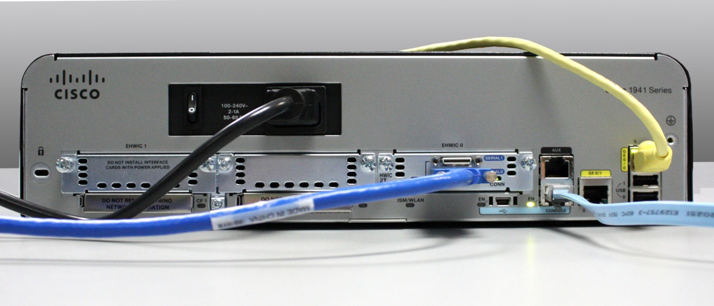
The following images highlight the activity and status lights of the front panel and backplane of a powered up and connected Cisco 1941 ISR.
Note: Some of the indicator lights are obscured from view in the image of the backplane of the Cisco 1941 router below.
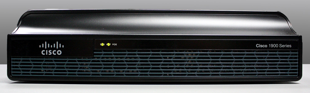
- In the top image above, examine the indicator lights on the front panel of the router? The lights are labeled SYS, ACT, and POE. What do the labels refer to? What do the lights in the image indicate about the status of the router? These labels would be readable if they were not lit.
____________________________________________________________________________________________________________________________________________________________________________________________________________________________________________________________
The SYS, ACT, and POE lights refer to: system status, network activity, and power over Ethernet. The lights in the image show that the router’s system is successfully powered on, that there is network activity, and that Power over Ethernet is not activated. - In the backplane image above, examine the indicator lights on the router. There are three visible activity lights, one for each of the connected interfaces and management ports. Examine the interface lights on your router. How are the lights labeled, and what is their meaning?____________________________________________________________________________________________________________________________________________________________________________________________________________________________________________________________
The lights in the image show that the serial and Gigabit Ethernet interfaces are active and that the Console management port is enabled and active. The Gigabit Ethernet interfaces have two lights each, one labeled S for sending and the other labeled L for link. The console port and mini USB console port have an EN label for enabled. The serial interfaces each have a light labeled Conn for connected. - Aside from the management ports and network interfaces, what other indicator lights are on the backplane of the router and what might their purpose be?____________________________________________________________________________________________________________________________________________________________________________________________________________________________________________________________
The backplane of the router also show CF0 and CF1 lights for the CompactFlash memory slots as well as an ISM/WLAN light which would indicate the presence of either a Cisco Internal Services Module or wireless LAN card.
Part 2: Examine Router Internal Characteristics Using Show Commands
Step 1: Establish a console connection to the router and use the show version command.
- Using Tera Term, console into the router and enter privileged EXEC mode using the enable command:
Router> enable
Router# - Display information about the router by using the show version command. Use the Spacebar on the keyboard to page through the output.
Router# show versionCisco IOS Software, C1900 Software (C1900-UNIVERSALK9-M), Version 15.2(4)M3, RELEASE SOFTWARE (fc1)Technical Support: http://www.cisco.com/techsupportCopyright (c) 1986-2011 by Cisco Systems, Inc.Compiled Thu 26-Jul-12 19:34 by prod_rel_teamROM: System Bootstrap, Version 15.0(1r)M15, RELEASE SOFTWARE (fc1)Router uptime is 1 day, 14 hours, 46 minutesSystem returned to ROM by power-onSystem restarted at 07:26:55 UTC Mon Dec 3 2012System image file is “flash0:c1900-universalk9-mz.SPA.152-4.M3.bin”Last reload type: Normal ReloadLast reload reason: power-on<output omitted>If you require further assistance please contact us by sending email to[email protected].Cisco CISCO1941/K9 (revision 1.0) with 487424K/36864K bytes of memory.Processor board ID FGL160823182 Gigabit Ethernet interfaces2 Serial(sync/async) interfaces1 terminal line1 Virtual Private Network (VPN) ModuleDRAM configuration is 64 bits wide with parity disabled.255K bytes of non-volatile configuration memory.250880K bytes of ATA System CompactFlash 0 (Read/Write)<output omitted>Technology Package License Information for Module:’c1900′
—————————————————————–
Technology Technology-package Technology-package
Current Type Next reboot
——————————————————————
ipbase ipbasek9 Permanent ipbasek9
security securityk9 Permanent securityk9
data None None None
Configuration register is 0x2102
- Based on the output of the show version command, answer the following questions about the router. If you are examining a different model router, include the information about it here.
- What is the version of the Cisco IOS and what is the system image filename?________________________________________________________________________________
IOS version 15.2(4)M3, c1900-universalk9-mz.SPA.152-4.M3.bin - What is the Bootstrap program version in ROM BIOS?________________________________________________________________________________
System Bootstrap version 15.0(1r)M15 - How long has the router been running without a restart (also known as its uptime)?________________________________________________________________________________
1 day, 14 hours, 46 minutes - How much dynamic random-access memory (DRAM) memory does the router have?________________________________________________________________________________
487424K/36864K = 512MB total - What is the router’s processor board ID number?________________________________________________________________________________
The processor board ID number is FGL16082318 - What network interfaces does the router have?________________________________________________________________________________
2 Gigabit Ethernet interfaces and 2 Serial interfaces - How much CompactFlash memory for IOS storage is there?________________________________________________________________________________
250880K of CompactFlash memory - How much nonvolatile random-access memory (NVRAM) memory for configuration file storage is there?________________________________________________________________________________
255K of NVRAM - What is the setting of the configuration register?________________________________________________________________________________
0x2102
- What is the version of the Cisco IOS and what is the system image filename?________________________________________________________________________________
Step 2: Use the show interface command to examine the network interfaces.
- Use the show interface gigabitEthernet 0/0 command to see the status of the Gigabit Ethernet 0/0 interface.
Note: After typing part of the command, for example, show interface g, you can use the Tab key on your keyboard to complete the gigabitEthernet command parameter.
Router# show interface gigabitEthernet 0/0GigabitEthernet0/0 is administratively down, line protocol is down Hardware is CN Gigabit Ethernet, address is 442b.031a.b9a0 (bia 442b.031a.b9a0) MTU 1500 bytes, BW 100000 Kbit/sec, DLY 100 usec, reliability 255/255, txload 1/255, rxload 1/255 Encapsulation ARPA, loopback not set Keepalive set (10 sec) Full Duplex, 100Mbps, media type is RJ45 output flow-control is unsupported, input flow-control is unsupported ARP type: ARPA, ARP Timeout 04:00:00 Last input never, output never, output hang never Last clearing of “show interface” counters never Input queue: 0/75/0/0 (size/max/drops/flushes); Total output drops: 0 Queueing strategy: fifo Output queue: 0/40 (size/max) 5 minute input rate 0 bits/sec, 0 packets/sec 5 minute output rate 0 bits/sec, 0 packets/sec 3 packets input, 276 bytes, 0 no buffer Received 0 broadcasts (0 IP multicasts)0 runts, 0 giants, 0 throttles
0 input errors, 0 CRC, 0 frame, 0 overrun, 0 ignored
0 watchdog, 0 multicast, 0 pause input
0 packets output, 0 bytes, 0 underruns
0 output errors, 0 collisions, 0 interface resets
0 unknown protocol drops
0 babbles, 0 late collision, 0 deferred
0 lost carrier, 0 no carrier, 0 pause output
0 output buffer failures, 0 output buffers swapped out
- Given the output of the show interface gigabitEthernet 0/0 command depicted above, or using the output from your router, answer the following questions:
What is the hardware type and MAC address of the Gigabit Ethernet interface?____________________________________________________________________________________
The hardware type is CN Gigabit Ethernet and the burned in address (bia) or MAC address is 442b.031a.b9a0
What is the interface media type? Is the interface up or down?____________________________________________________________________________________
According to the output the interface media type is RJ45 and the Gigabit Ethernet interface is administratively down and the line protocol is down. - Use the show interfaces serial 0/0/0 command to view the status of the Serial 0/0/0 interface.
Router# show interface serial 0/0/0Serial0/0/0 is administratively down, line protocol is down Hardware is WIC MBRD Serial MTU 1500 bytes, BW 1544 Kbit/sec, DLY 20000 usec, reliability 255/255, txload 1/255, rxload 1/255 Encapsulation HDLC, loopback not set Keepalive set (10 sec) Last input 07:41:21, output never, output hang never Last clearing of “show interface” counters never Input queue: 0/75/0/0 (size/max/drops/flushes); Total output drops: 0 Queueing strategy: fifo Output queue: 0/40 (size/max) 5 minute input rate 0 bits/sec, 0 packets/sec 5 minute output rate 0 bits/sec, 0 packets/sec1 packets input, 24 bytes, 0 no buffer
Received 1 broadcasts (0 IP multicasts)
0 runts, 0 giants, 0 throttles
0 input errors, 0 CRC, 0 frame, 0 overrun, 0 ignored, 0 abort
0 packets output, 0 bytes, 0 underruns
0 output errors, 0 collisions, 2 interface resets
0 unknown protocol drops
0 output buffer failures, 0 output buffers swapped out
1 carrier transitions
DCD=down DSR=down DTR=down RTS=down CTS=down
- Given the output command depicted above, answer the following questions:
What is the frame encapsulation type?
___________________________________________________________________________________
According to the output above, the frame encapsulation type is HDLC.
What is the hardware type? Is the interface up or down?___________________________________________________________________________________
The hardware type is WIC MBRD Serial and the interface is administratively down and line protocol down.
Reflection
- Why might you need to use an EHWIC expansion slot?_______________________________________________________________________________________
Answers will vary. You may need to have a WAN connection to your ISP over a WAN interface technology that does not come with the router by default. - Why might you need to upgrade the Flash memory?_______________________________________________________________________________________
Answers will vary. You may want to store an additional IOS image file or upgrade to a larger IOS image. - What is the purpose of the mini-USB port?_____________________________________________________________________________________________________________________________________________________________________________________________________________________________________________________________________
The purpose of the mini USB port is to give you the ability to console into the router if you do not have a COM serial port on your laptop or computer. - What is the purpose of the ISM/WLAN indicator light on the backplane of the router? What does it refer to?____________________________________________________________________________________________________________________________________________________________________________________________________________________________________________________________________________________________________________________________________________________________
The Cisco 1941 router can support a Cisco Internal Services Module that can enhance the intelligence and abilities of the router to perform activities like intrusion prevention scanning. The Cisco 1941 router can also be equipped with a Wireless LAN card for supporting wireless local area networks.