Last Updated on January 30, 2019 by Admin
7.2.5.4 Lab – Configuring IPv6 Addresses on Network Devices Answers
Lab – Configuring IPv6 Addresses on Network Devices (Answers Version)
Answers Note: Red font color or gray highlights indicate text that appears in the instructor copy only.
Topology

Addressing Table
| Device | Interface | IPv6 Address | Prefix Length | Default Gateway |
| R1 | G0/0 | 2001:DB8:ACAD:A::1 | 64 | N/A |
| G0/1 | 2001:DB8:ACAD:1::1 | 64 | N/A | |
| S1 | VLAN 1 | 2001:DB8:ACAD:1::B | 64 | N/A |
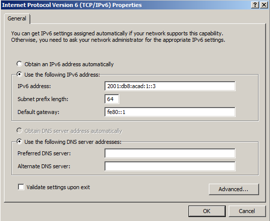
| PC-A | NIC | 2001:DB8:ACAD:1::3 | 64 | FE80::1 |
| PC-B | NIC | 2001:DB8:ACAD:A::3 | 64 | FE80::1 |
Objectives
Part 1: Set Up Topology and Configure Basic Router and Switch Settings
Part 2: Configure IPv6 Addresses Manually
Part 3: Verify End-to-End Connectivity
Background / Scenario
Knowledge of the Internet Protocol version 6 (IPv6) multicast groups can be helpful when assigning IPv6 addresses manually. Understanding how the all-router multicast group is assigned and how to control address assignments for the Solicited Nodes multicast group can prevent IPv6 routing issues and help ensure best practices are implemented.
In this lab, you will configure hosts and device interfaces with IPv6 addresses and explore how the all-router multicast group is assigned to a router. You will use show commands to view IPv6 unicast and multicast addresses. You will also verify end-to-end connectivity using the ping and traceroute commands.
Note: The routers used with CCNA hands-on labs are Cisco 1941 ISRs with Cisco IOS Release 15.2(4)M3 (universalk9 image). The switches used are Cisco Catalyst 2960s with Cisco IOS Release 15.0(2) (lanbasek9 image). Other routers, switches and Cisco IOS versions can be used. Depending on the model and Cisco IOS version, the commands available and output produced might vary from what is shown in the labs. Refer to the Router Interface Summary table at the end of the lab for the correct interface identifiers.
Note: Make sure that the routers and switches have been erased and have no startup configurations. If you are unsure, contact your instructor.
Answers Note: Refer to the Answers Lab Manual for the procedures to initialize and reload devices.
Answers Note: The default bias template used by the Switch Database Manager (SDM) does not provide IPv6 address capabilities. Verify that SDM is using either the dual-ipv4-and-ipv6 template or the lanbase-routing template. The new template will be used after reboot even if the config is not saved.
S1# show sdm prefer
Follow these steps to assign the dual-ipv4-and-ipv6 template as the default SDM template:
S1# configure terminal
S1(config)# sdm prefer dual-ipv4-and-ipv6 default
S1(config)# end
S1# reload
Required Resources
- 1 Router (Cisco 1941 with Cisco IOS software, Release 15.2(4)M3 universal image or comparable)
- 1 Switch (Cisco 2960 with Cisco IOS Release 15.0(2) lanbasek9 image or comparable)
- 2 PCs (Windows 7 or 8 with terminal emulation program, such as Tera Term)
- Console cables to configure the Cisco IOS devices via the console ports
- Ethernet cables as shown in the topology
Note: The Gigabit Ethernet interfaces on Cisco 1941 routers are autosensing and an Ethernet straight-through cable may be used between the router and PC-B. If using another model Cisco router, it may be necessary to use an Ethernet crossover cable.
Part 1: Set Up Topology and Configure Basic Router and Switch Settings
Step 1: Cable the network as shown in the topology.
Step 2: Initialize and reload the router and switch.
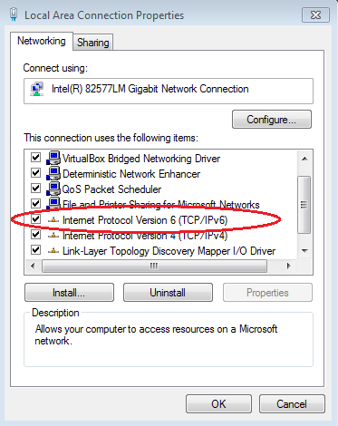
Step 3: Verify that the PC interfaces are configured to use the IPv6 protocol.
Verify that the IPv6 protocol is active on both PCs by ensuring that the Internet Protocol Version 6 (TCP/IPv6) check box is selected in the Local Area Connection Properties window.
Step 4: Configure the router.
- Console into the router and enable privileged EXEC mode.
- Assign the device name to the router.
- Disable DNS lookup to prevent the router from attempting to translate incorrectly entered commands as though they were hostnames.
- Assign class as the privileged EXEC encrypted password.
- Assign cisco as the console password and enable login.
- Assign cisco as the VTY password and enable login.
- Encrypt the clear text passwords.
- Create a banner that warns anyone accessing the device that unauthorized access is prohibited.
- Save the running configuration to the startup configuration file.
Step 5: Configure the switch.
- Console into the switch and enable privileged EXEC mode.
- Assign the device name to the switch.
- Disable DNS lookup to prevent the router from attempting to translate incorrectly entered commands as though they were hostnames.
- Assign class as the privileged EXEC encrypted password.
- Assign cisco as the console password and enable login.
- Assign cisco as the VTY password and enable login.
- Encrypt the clear text passwords.
- Create a banner that warns anyone accessing the device that unauthorized access is prohibited.
- Save the running configuration to the startup configuration file.
Part 2: Configure IPv6 Addresses Manually
Step 1: Assign the IPv6 addresses to Ethernet interfaces on R1.
- Assign the IPv6 global unicast addresses, listed in the Addressing Table, to both Ethernet interfaces on R1.
R1(config)# interface g0/0R1(config-if)# ipv6 address 2001:db8:acad:a::1/64R1(config-if)# no shutdownR1(config-if)# interface g0/1R1(config-if)# ipv6 address 2001:db8:acad:1::1/64R1(config-if)# no shutdownR1(config-if)# end
R1#
Answers Note: The IPv6 global prefix 2001:DB8::/32 is a reserved prefix for use in documentation, as described in RFC 3849.
- Issue the show ipv6 interface brief command to verify that the correct IPv6 unicast address is assigned to each interface.
R1# show ipv6 interface briefEm0/0 [administratively down/down] unassignedGigabitEthernet0/0 [up/up] FE80::D68C:B5FF:FECE:A0C02001:DB8:ACAD:A::1
GigabitEthernet0/1 [up/up]
FE80::D68C:B5FF:FECE:A0C1
2001:DB8:ACAD:1::1
<output omitted>
- Issue the show ipv6 interface g0/0 command. Notice that the interface is listing two Solicited Nodes multicast groups, because the IPv6 link-local (FE80) Interface ID was not manually configured to match the IPv6 unicast Interface ID.
Note: The link-local address displayed is based on EUI-64 addressing, which automatically uses the interface Media Access Control (MAC) address to create a 128-bit IPv6 link-local address.
R1# show ipv6 interface g0/0GigabitEthernet0/0 is up, line protocol is up IPv6 is enabled, link-local address is FE80::D68C:B5FF:FECE:A0C0 No Virtual link-local address(es):Global unicast address(es):
2001:DB8:ACAD:A::1, subnet is 2001:DB8:ACAD:A::/64
Joined group address(es):
FF02::1
FF02::1:FF00:1
FF02::1:FFCE:A0C0
MTU is 1500 bytes
<output omitted>
- To get the link-local address to match the unicast address on the interface, manually enter the link-local addresses on each of the Ethernet interfaces on R1.
R1# config tEnter configuration commands, one per line. End with CNTL/Z.R1(config)# interface g0/0R1(config-if)# ipv6 address fe80::1 link-local
R1(config-if)# interface g0/1
R1(config-if)# ipv6 address fe80::1 link-local
R1(config-if)# end
R1#
Note: Each router interface belongs to a separate network. Packets with a link-local address never leave the local network; therefore, you can use the same link-local address on both interfaces.
- Re-issue the show ipv6 interface g0/0 command. Notice that the link-local address has been changed to FE80::1 and that there is only one Solicited Nodes multicast group listed.
R1# show ipv6 interface g0/0GigabitEthernet0/0 is up, line protocol is up IPv6 is enabled, link-local address is FE80::1No Virtual link-local address(es):
Global unicast address(es):
2001:DB8:ACAD:A::1, subnet is 2001:DB8:ACAD:A::/64
Joined group address(es):
FF02::1
FF02::1:FF00:1
MTU is 1500 bytes
<output omitted>
What multicast groups have been assigned to interface G0/0?____________________________________________________________________________________
The all-nodes multicast group (FF02::1) and the Solicited Nodes multicast group (FF02::1:FF00:1).
Step 2: Enable IPv6 routing on R1.
- On a PC-B command prompt, enter the ipconfig command to examine IPv6 address information assigned to the PC interface.
Has an IPv6 unicast address been assigned to the network interface card (NIC) on PC-B? _________ No - Enable IPv6 routing on R1 using the IPv6 unicast-routing command.
R1 # configure terminalR1(config)# ipv6 unicast-routingR1(config)# exitR1#
*Dec 17 18:29:07.415: %SYS-5-CONFIG_I: Configured from console by console
- Use the show ipv6 interface g0/0 command to see what multicast groups are assigned to interface G0/0. Notice that the all-router multicast group (FF02::2) now appears in the group list for interface G0/0.
Note: This will allow the PCs to obtain their IP address and default gateway information automatically using Stateless Address Autoconfiguration (SLAAC).
R1# show ipv6 interface g0/0GigabitEthernet0/0 is up, line protocol is up IPv6 is enabled, link-local address is FE80::1No Virtual link-local address(es):
Global unicast address(es):
2001:DB8:ACAD:A::1, subnet is 2001:DB8:ACAD:A::/64 [EUI]
Joined group address(es):
FF02::1
FF02::2
FF02::1:FF00:1
MTU is 1500 bytes
<output omitted>
- Now that R1 is part of the all-router multicast group, re-issue the ipconfig command on PC-B. Examine the IPv6 address information.
Why did PC-B receive the Global Routing Prefix and Subnet ID that you configured on R1?________________________________________________________________________________________________________________________________________________________________________
R1 G0/0 is now part of the All-router multicast group, FF02::2. This allows it to send Router Advertisement (RA) messages with the Global Network Address and Subnet ID information to all nodes on the LAN. Notice that it also sent the link-local address, FE80::1, as the Default Gateway. The PCs will receive their IP address and default gateway via SLAAC.
Step 3: Assign IPv6 addresses to the management interface (SVI) on S1.
- Assign the IPv6 address listed in the Addressing Table to the management interface (VLAN 1) on S1. Also assign a link-local address for this interface. IPv6 command syntax is the same as on the router.
S1(config)# interface vlan 1S1(config-if)# ipv6 address 2001:db8:acad:1::b/64S1(config-if)# ipv6 address fe80::b link-localS1(config-if)# end
S1#
*Mar 1 03:25:26.681: %SYS-5-CONFIG_I: Configured from console by console
- Verify that the IPv6 addresses are properly assigned to the management interface using the show ipv6 interface vlan1 command.
S1# show ipv6 interface vlan1Vlan1 is up, line protocol is up IPv6 is enabled, link-local address is FE80::B No Virtual link-local address(es): Global unicast address(es): 2001:DB8:ACAD:1::B, subnet is 2001:DB8:ACAD:1::/64 Joined group address(es): FF02::1 FF02::1:FF00:B MTU is 1500 bytes ICMP error messages limited to one every 100 millisecondsICMP redirects are enabled
ICMP unreachables are sent
Output features: Check hwidb
ND DAD is enabled, number of DAD attempts: 1
ND reachable time is 30000 milliseconds (using 30000)
ND NS retransmit interval is 1000 milliseconds
S1#
Note: The default 2960 Switch Database Manager (SDM) template does not support IPv6. It may be necessary to issue the command sdm prefer dual-ipv4-and-ipv6 default to enable IPv6 addressing before applying an IPv6 address to the VLAN 1 SVI.
Step 4: Assign static IPv6 addresses to the PCs.
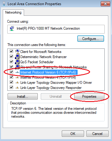
- Open the Local Area Connection Properties window on PC-A. Select Internet Protocol Version 6 (TCP/IPv6) and click Properties.
- Click the Use the following IPv6 address radio button. Refer to the Addressing Table and enter the IPv6 address, Subnet prefix length, and Default gateway information. Click OK.
- Click Close to close the Local Area Connection Properties window.
- Repeat Steps 4a to c to enter the static IPv6 information on PC-B. For the correct IPv6 address information, refer to the Addressing Table.
- Issue the ipconfig command from the command line on PC-B to verify the IPv6 address information.
Part 3: Verify End-to-End Connectivity
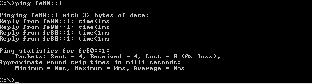
- From PC-A, ping FE80::1. This is the link-local address assigned to G0/1 on R1.
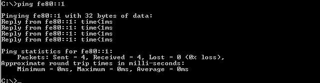 Note: You can also test connectivity by using the global unicast address, instead of the link-local address.
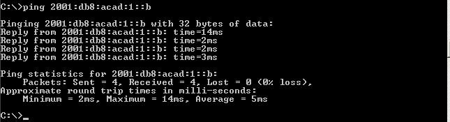
 - Ping the S1 management interface from PC-A.
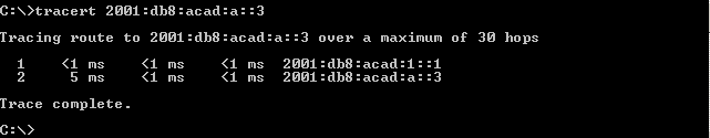
- Use the tracert command on PC-A to verify that you have end-to-end connectivity to PC-B.
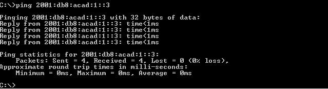
- From PC-B, ping PC-A.
- From PC-B, ping the link-local address for G0/0 on R1.
 Note: If end-to-end connectivity is not established, troubleshoot your IPv6 address assignments to verify that you entered the addresses correctly on all devices.
Reflection
- Why can the same link-local address, FE80::1, be assigned to both Ethernet interfaces on R1?______________________________________________________________________________________________________________________________________________________________________________
Link-local packets never leave the local network, so the same link-local address can be used on an interface associated to a different local network. - What is the Subnet ID of the IPv6 unicast address 2001:db8:acad::aaaa:1234/64?_______________________________________________________________________________________
0 (zero) or 0000 (zeros). The 4th hextet is the Subnet ID of an IPv6 address with a prefix of /64. In the example the 4th hextet contains all zeros and the IPv6 Omitting All 0 Segment rule is using the double colon to depict the Subnet ID and the first two hextets of the Interface ID.
Router Interface Summary Table
| Router Interface Summary | ||||
| Router Model | Ethernet Interface #1 | Ethernet Interface #2 | Serial Interface #1 | Serial Interface #2 |
| 1800 | Fast Ethernet 0/0 (F0/0) | Fast Ethernet 0/1 (F0/1) | Serial 0/0/0 (S0/0/0) | Serial 0/0/1 (S0/0/1) |
| 1900 | Gigabit Ethernet 0/0 (G0/0) | Gigabit Ethernet 0/1 (G0/1) | Serial 0/0/0 (S0/0/0) | Serial 0/0/1 (S0/0/1) |
| 2801 | Fast Ethernet 0/0 (F0/0) | Fast Ethernet 0/1 (F0/1) | Serial 0/1/0 (S0/0/0) | Serial 0/1/1 (S0/0/1) |
| 2811 | Fast Ethernet 0/0 (F0/0) | Fast Ethernet 0/1 (F0/1) | Serial 0/0/0 (S0/0/0) | Serial 0/0/1 (S0/0/1) |
| 2900 | Gigabit Ethernet 0/0 (G0/0) | Gigabit Ethernet 0/1 (G0/1) | Serial 0/0/0 (S0/0/0) | Serial 0/0/1 (S0/0/1) |
| Note: To find out how the router is configured, look at the interfaces to identify the type of router and how many interfaces the router has. There is no way to effectively list all the combinations of configurations for each router class. This table includes identifiers for the possible combinations of Ethernet and Serial interfaces in the device. The table does not include any other type of interface, even though a specific router may contain one. An example of this might be an ISDN BRI interface. The string in parenthesis is the legal abbreviation that can be used in Cisco IOS commands to represent the interface. | ||||
Device Configs
Router R1 (After part 1 of this lab)
R1#sh run
Building configuration…
Current configuration : 1443 bytes
!
version 15.2
service timestamps debug datetime msec
service timestamps log datetime msec
service password-encryption
!
hostname R1
!
boot-start-marker
boot-end-marker
!
!
enable secret 4 06YFDUHH61wAE/kLkDq9BGho1QM5EnRtoyr8cHAUg.2
!
no aaa new-model
memory-size iomem 15
!
no ip domain lookup
ip cef
no ipv6 cef
multilink bundle-name authenticated
!
!
interface Embedded-Service-Engine0/0
no ip address
shutdown
!
interface GigabitEthernet0/0
no ip address
shutdown
duplex auto
speed auto
!
interface GigabitEthernet0/1
no ip address
shutdown
duplex auto
speed auto
!
interface Serial0/0/0
no ip address
shutdown
clock rate 2000000
!
interface Serial0/0/1
no ip address
shutdown
!
ip forward-protocol nd
!
no ip http server
no ip http secure-server
!
control-plane
!
banner motd ^C
**********************************************
* Warning: Unauthorized access is prohibited! *
**********************************************
^C
!
line con 0
password 7 01100F175804
login
line aux 0
line 2
no activation-character
no exec
transport preferred none
transport input all
transport output pad telnet rlogin lapb-ta mop udptn v120 ssh
stopbits 1
line vty 0 4
password 7 104D000A0618
login
transport input all
!
scheduler allocate 20000 1000
!
end
Switch S1 (After part 1 of this lab)
S1#sh run
Building configuration…
Current configuration : 1624 bytes
!
version 15.0
no service pad
service timestamps debug datetime msec
service timestamps log datetime msec
service password-encryption
!
hostname S1
!
boot-start-marker
boot-end-marker
!
enable secret 4 06YFDUHH61wAE/kLkDq9BGho1QM5EnRtoyr8cHAUg.2
!
no aaa new-model
system mtu routing 1500
!
!
no ip domain-lookup
!
spanning-tree mode pvst
spanning-tree extend system-id
!
vlan internal allocation policy ascending
!
interface FastEthernet0/1
shutdown
!
interface FastEthernet0/2
shutdown
!
interface FastEthernet0/3
shutdown
!
interface FastEthernet0/4
shutdown
!
interface FastEthernet0/5
!
interface FastEthernet0/6
!
interface FastEthernet0/7
!
interface FastEthernet0/8
!
interface FastEthernet0/9
!
interface FastEthernet0/10
!
interface FastEthernet0/11
!
interface FastEthernet0/12
!
interface FastEthernet0/13
!
interface FastEthernet0/14
!
interface FastEthernet0/15
!
interface FastEthernet0/16
!
interface FastEthernet0/17
!
interface FastEthernet0/18
!
interface FastEthernet0/19
!
interface FastEthernet0/20
!
interface FastEthernet0/21
!
interface FastEthernet0/22
!
interface FastEthernet0/23
!
interface FastEthernet0/24
!
interface GigabitEthernet0/1
!
interface GigabitEthernet0/2
!
interface Vlan1
no ip address
!
ip http server
ip http secure-server
!
banner motd ^C
**********************************************
* Warning: Unauthorzed access is prohibited! *
**********************************************
^C
!
line con 0
password 7 121A0C041104
login
line vty 0 4
password 7 121A0C041104
login
line vty 5 15
password 7 121A0C041104
login
!
end
Router R1 (Final)
R1#show run
Building configuration…
Current configuration : 1577 bytes
!
version 15.2
service timestamps debug datetime msec
service timestamps log datetime msec
service password-encryption
!
hostname R1
!
boot-start-marker
boot-end-marker
!
enable secret 4 06YFDUHH61wAE/kLkDq9BGho1QM5EnRtoyr8cHAUg.2
!
no aaa new-model
memory-size iomem 15
!
no ip domain lookup
ip cef
ipv6 unicast-routing
ipv6 cef
multilink bundle-name authenticated
!
!
interface Embedded-Service-Engine0/0
no ip address
shutdown
!
interface GigabitEthernet0/0
no ip address
duplex auto
speed auto
ipv6 address FE80::1 link-local
ipv6 address 2001:DB8:ACAD:A::1/64
!
interface GigabitEthernet0/1
no ip address
duplex auto
speed auto
ipv6 address FE80::1 link-local
ipv6 address 2001:DB8:ACAD:1::1/64
!
interface Serial0/0/0
no ip address
shutdown
clock rate 2000000
!
interface Serial0/0/1
no ip address
shutdown
!
ip forward-protocol nd
!
no ip http server
no ip http secure-server
!
control-plane
!
banner motd ^C
**********************************************
* Warning: Unauthorzed access is prohibited! *
**********************************************
^C
!
line con 0
password 7 01100F175804
login
line aux 0
line 2
no activation-character
no exec
transport preferred none
transport input all
transport output pad telnet rlogin lapb-ta mop udptn v120 ssh
stopbits 1
line vty 0 4
password 7 104D000A0618
login
transport input all
!
scheduler allocate 20000 1000
!
end
Switch S1 (Final)
S1#sh run
Building configuration…
Current configuration : 1733 bytes
!
!
version 15.0
no service pad
service timestamps debug datetime msec
service timestamps log datetime msec
service password-encryption
!
hostname S1
!
boot-start-marker
boot-end-marker
!
enable secret 4 06YFDUHH61wAE/kLkDq9BGho1QM5EnRtoyr8cHAUg.2
!
no aaa new-model
system mtu routing 1500
!
no ip domain-lookup
!
spanning-tree mode pvst
spanning-tree extend system-id
!
vlan internal allocation policy ascending
!
interface FastEthernet0/1
shutdown
!
interface FastEthernet0/2
shutdown
!
interface FastEthernet0/3
shutdown
!
interface FastEthernet0/4
shutdown
!
interface FastEthernet0/5
!
interface FastEthernet0/6
!
interface FastEthernet0/7
!
interface FastEthernet0/8
!
interface FastEthernet0/9
!
interface FastEthernet0/10
!
interface FastEthernet0/11
!
interface FastEthernet0/12
!
interface FastEthernet0/13
!
interface FastEthernet0/14
!
interface FastEthernet0/15
!
interface FastEthernet0/16
!
interface FastEthernet0/17
!
interface FastEthernet0/18
!
interface FastEthernet0/19
!
interface FastEthernet0/20
!
interface FastEthernet0/21
!
interface FastEthernet0/22
!
interface FastEthernet0/23
!
interface FastEthernet0/24
!
interface GigabitEthernet0/1
!
interface GigabitEthernet0/2
!
interface Vlan1
no ip address
ipv6 address FE80::B link-local
ipv6 address 2001:DB8:ACAD:1::B/64
!
ip http server
ip http secure-server
!
!
banner motd ^C
**********************************************
* Warning: Unauthorzed access is prohibited! *
**********************************************
^C
!
line con 0
password 7 121A0C041104
login
line vty 0 4
password 7 121A0C041104
login
line vty 5 15
password 7 121A0C041104
login
!
end